BA1404 is enough for general FM transmission, but it has a fatal disadvantage: there is no phase-locked loop circuit, that is, PLL, and it is easy to run the frequency! It is not suitable for places with higher requirements. To this end, the majority of FM enthusiasts have made suggestions to add a phase-locked loop circuit for it. There are universal digital integrated circuits 4000 series + 74 series and some special high-frequency phase-locked loop circuits such as MC145152 and MC145170. These circuits are very complicated, and debugging is cumbersome and difficult to succeed!
Rohm also realized this and launched the BH1414-1417 series! Equivalent to BA1404 + PLL, it really provides an excellent opportunity for everyone.
The production materials are now announced, and I wish you all success!
Design of NC Frequency Modulation Transmitter
Abstract: The new digital FM transmitter has the characteristics of stable frequency and arbitrarily settable transmission frequency in the range of 88.0 MHZ to 110.0 MHZ. This paper introduces the design method of the digital FM transmitter controlled by AT89C52 microcontroller.
Keywords: single chip microcomputer digital control BH1415F FM transmission Introduction:
At present, FM broadcast transmitters used in most colleges and universities have a single fixed transmission frequency and poor stability. This article designs a digitally controlled FM transmitter that can arbitrarily set the transmission frequency within the range of 88.0 MHZ to 110.0 MHZ. It can preset 11 channels. The minimum transmission frequency adjustment is 0.1 MHZ. The application is more flexible and reliable, and can be widely used in school wireless broadcasting, TV live guide, car navigation, wireless speech, etc.
1 System hardware design
1. One-chip computer control part The one-chip computer adopts AT89C52, adopts the minimal application system design, P0 port and P2 port are used as common positive LED digital tube driver, P1 port is used as a 16-key keyboard interface, among which T0-T3 are hundred, ten respectively Frequency operation keys for digits, single digits and decimal places, T4—T14 are the preset keys for the transmission frequency, and T15 are the mono / stereo control keys. P3.0, P3.1, P3.2 as the communication port with HB1415, used to transmit the transmission frequency control data, P3.3 is used for stereo transmission instructions. Adopt 12MHZ crystal oscillator to simulate serial communication. The single-chip microcomputer control circuit is shown in Figure 1.
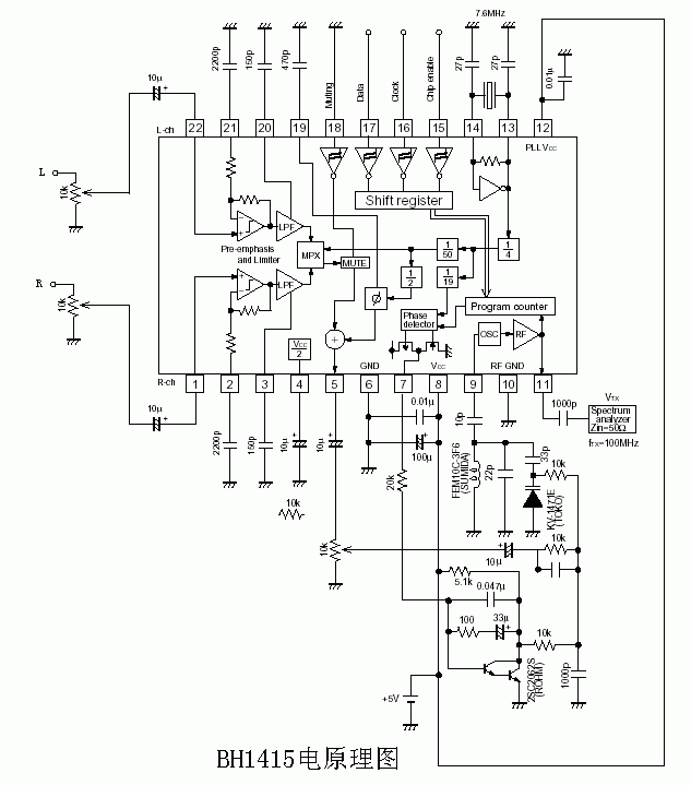
1.2 The FM modulation transmission part adopts the latest FM transmission dedicated integrated circuit BH1415F produced by Rohm Company, which contains stereo signal modulation, FM broadcast signal transmission circuit, BH1415F has pre-compensation circuit, limiter circuit, low-pass filter circuit, etc. Therefore, it has a good timbre, built-in PLL system FM transmission circuit, the transmission frequency is very stable. The FM transmission frequency can be directly controlled by the single-chip microcomputer through the serial port. The function of each pin of BH1415F is shown in Table 1, and the application circuit is shown in Figure 2. Lose from pin 11 Table 1
Foot foot description DC (V)
1 Right channel input: connect to the right channel audio signal through a capacitor 1 / 2VCC
2 Left audio source input terminal: connected to the left channel audio signal through a capacitor
2,21 Time constant terminal: it connects a capacitor with time constant τ = 22.7kΩC
3,20 LPF time constant end: this is 15KHz LPF. It is connected to 150P capacitor 1 / 2VCC
4 Filter end: it is the reference voltage of the audio part filter 1 / 2VCC
5 Stereo composite signal output: it is connected to the FM modulator 1 / 2VCC
6 Ground GND
7 PLL phase detector output: it is connected to the PLL LPF circuit-
8 Power supply terminal Vcc
9 RF oscillator terminal: This is the base terminal of the oscillator, which is connected to the oscillation time constant 4 / 7Vcc
10 RF ground GND
11 RF transmission output Vcc-1.9
12 PLL power supply terminal Vcc
13,14 X'tal oscillator side: it is connected to a 7.6MHz crystal-
15 Chip authorization terminal: continuous input of high-level data
16 Clock input: The clock with data and synchronization is input in sequence data.
17 Data input
18 Mute terminal: 0.8Vcc≤ Pin18: Mute ON 0.2VCC≥ Pin18: Mute OFF
19 Control signal adjustment terminal 1 / 2Vcc
The resulting FM modulation signal is transmitted by the antenna after high-frequency amplification, and the power of the post-stage high-frequency amplifier can be considered according to the distance range received.
1. 3 Power system The power consumption of the digital frequency control station controlled by the single-chip computer is very small, and the 7805 three-terminal voltage regulator block can be used to separately power the single-chip computer and the BH1415F circuit. The power of the power transformer can be greater than 10W. The power supply pin of the integrated block should be connected with a 0.1μF ceramic capacitor nearby.
2 SCM software design
2.1 Main program module
1) Keyboard scanning program: using 4 * 4 determinant query method.
2) Display program: display 4 frequency digital value by dynamic scanning method.
3) Serial communication program: It consists of decimal BCD code to binary program, 16-bit frequency control byte synthesis program, and simulated asynchronous serial transmission program.
2.2 BH1415F serial communication format
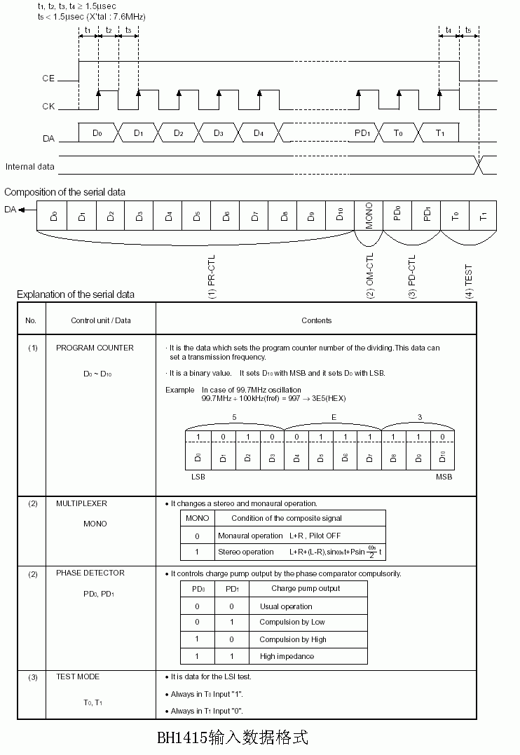
The frequency control code of BH1415F is 16 bits, and its transmission format requirements are shown in Figure 3. Among them, D0-D10 is frequency control data, and its value multiplied by 0.1 is the output frequency (unit MHZ) of BH1415F.
D11-D15 are control bits, of which D11 (MONO) bit is a mono / stereo control bit, when 0 is mono transmission mode, 1 is stereo transmission mode. The D12 (PD0) and D13 (PD1) bits are used for phase control, usually 0. When they are 01 and 10 respectively, the transmission frequency can be at the lowest and highest places. D14 (T0) and D15 (T1) are used for test mode control, usually 00, when it is 10, it is test mode. The following is the control byte sending source program used for the communication between the microcontroller and the BH1415F:
PUT: MOV R3, # 8; send 8-bit control CLR C; clear C
PUT1: RRC A; right shift with carry (first low)
MOV P3.0, C; low bit sent to P3.0 port NOP; delay 4 microsecond NOP;
NOP;
NOP;
SETB P3.1; latch data (latching data on rising edge)
NOP; Delay 4 microseconds NOP;
NOP;
NOP;
CLR P3.1;
DJNZ R3, PUT1; 8 digits are not sent to PUT1 and then sent
RET; End of sending 8 bits
3 Summary The single-chip microcomputer numerical control FM transmitter is easy to design and manufacture, small in size, high in performance and reliability, and is an ideal choice for low-power FM transmission.
Reference materials:
[1] ROHM CO., LTD 2000. —BH1415F.pdf
[2] Atmel CorporaTIon 1999. —AT89C52.pdf 

For more knowledge of PLL, please visit http: //PLL.html
What is Graphic Overlay?
Graphic Overlay is A thin polyester or polycarbonate substrate that acts as the top layer of a membrane switch.
Normally,it is silk screen printed or digitally printed onto the second (back) surface,
then adhesive is applied to the back for easy application.
Printing on the second surface allows the substrate to protect the printing from damage.
This process distinguishes an overlay from a label.
Graphic Overlay,Panel Mount Tactile Switch,Custom Front Panel Membrane,Panel Tactile Switch Membrane
CIXI MEMBRANE SWITCH FACTORY , https://www.cnjunma.com