The ABS/ASR/VDC integrated system integrated with the anti-lock Braking System (ABS), the Acceleration Slip Regulation System (ASR) and the Vehicle Dynamic Control System (VDC) is One of the core devices of the automotive active safety control system. The system can significantly improve the vehicle's braking performance, driveability, steering maneuverability and lateral stability, reduce tire wear and accident risk, increase driving safety and driving portability [1].
This article refers to the address: http://
In order to improve the reliability of the system, the world's major automakers or component manufacturers are equipped with fault diagnosis systems in the ABS/ASR/VDC products. The system monitors the working condition of the ABS/ASR/VDC system through online testing of the status parameters of the electrical components, and realizes the system self-diagnosis.
The main faults common in ABS/ASR/VDC systems occur in solenoid valves, wheel speed sensors, power supplies, electronic control unit ECU (Electronic Control Unit), solenoid valve master switches, etc. [2]. In the ABS/ASR/VDC fault diagnosis system, it is necessary to monitor the regulated power supply, the wheel speed processing circuit, the solenoid valve drive circuit, and the solenoid valve master switch. When the ABS/ASR/VDC system fails, the main solenoid switch is turned off, the ABS/ASR/VDC is taken out of service, the normal brake and drive are restored, and the fault code is stored for maintenance. The fault code can be displayed in different ways: the fault code is flashed by the fault warning light of the instrument panel; the digital code and information data of the fault code are directly displayed by the display on the instrument panel; connected to the diagnostic seat with a dedicated fault detector, read Take the fault code [3].
The fault diagnosis process of the ABS/ASR/VDC system equipped in modern cars can generally be divided into three stages [4]: ​​(1) static self-test of the system; (2) dynamic self-test when the car starts; (3) car driving Timed dynamic self-test in.
1 Fault diagnosis circuit for key components of ABS/ASR/VDC system
ABS/ASR/VDC system ECU mainly realizes the functions of wheel speed signal acquisition and processing, control software storage and operation, pressure regulator solenoid valve drive and communication with other ECUs or computers. At present, several major ABS/ASR/VDC system manufacturers in the world have adopted the overall design scheme of the main and auxiliary dual MCUs: the main MCU is mainly responsible for signal acquisition and calculation processing, and generates corresponding control commands according to the control logic to output to the system actuator. The auxiliary MCU is mainly responsible for detecting the running status of the main MCU, and has certain fault detection and emergency processing functions. When it is detected that the main MCU cannot work normally or finds a fault, the ABS/ASR/VDC promptly exits the control and resumes the normal braking and driving. This paper studies and designs an ABS/ASR/VDC fault diagnosis system based on dual MCU architecture.
1.1 Solenoid valve fault diagnosis circuit
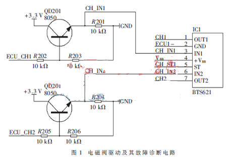
After analyzing and processing the wheel speed input data, the MCU outputs a corresponding control signal after a certain control logic. The control signal must be power amplified to drive the actuator. The main function of the driver circuit is to convert the TTL level of the MCU output to the drive level required by the actuator, and to amplify a small current enough to drive the actuator. In addition, due to the large current and rapid change of the driving actuator, improper handling will greatly interfere with the power supply voltage and cause large fluctuations. In order to reduce interference, electrical isolation between the driver circuit and other circuits is performed. The drive circuit is provided with a fault monitoring circuit to monitor the working state of the solenoid valve in real time and feed back the fault information to the MCU in time. The solenoid valve drive and its fault diagnosis circuit are shown in Figure 1.
1.2 Wheel speed sensor fault diagnosis circuit
The static fault of the magnetoelectric wheel speed sensor includes short circuit and open circuit of the electromagnetic coil inside the sensor. The system can judge and monitor through the hardware fault diagnosis circuit during self-test. In this paper, a voltage divider circuit is designed to reflect the internal resistance of the sensor by measuring the voltage divider value on the electromagnetic coil of the sensor to determine whether there is a short circuit or open circuit fault. Select CD4066 (four-channel bidirectional analog switch) to control the voltage divider circuit and wheel speed signal output time-sharing operation. The total voltage of the voltage divider circuit is +5 V, which is connected to the resistor R, the chip CD4066, the internal resistance of the sensor and the ground to form a loop. Figure 2 shows the circuit diagram of the wheel speed sensor fault diagnosis.
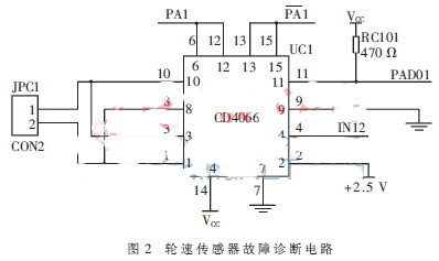
The working principle of the circuit is that when PA1 outputs a high level, pins 6 and 12 are high, control pins 8 and 9 and pins 10 and 11 are both turned on. At this time, the +5 V power supply voltage passes through RC101 and CD4066. The internal resistance and the internal resistance of the sensor form a loop. The voltage value at PAD01 indirectly reflects the internal resistance of the sensor. It is connected to the AD conversion channel of the auxiliary MCU. The conversion value is 3.05 V for the short-circuit voltage limit and 4.5 V for the open circuit voltage limit. The comparison can infer whether the sensor is short-circuited or open-circuited; when the output of PA1 is low, the output of PA1 goes high through the inverter, input to pins 13, 15 and control pins 1 and 2 and pin 3. Both and 4 are turned on, so that the wheel speed signal output by the sensor enters the wheel speed processing circuit.
1.3 MCU fault diagnosis circuit design
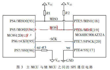
In order to ensure the safe and reliable operation of the main MCU, a SPI (Serial Peripheral Interface) interface communication circuit is designed, and the auxiliary MCU monitors the main MCU through communication. SPI is a high-speed and high-efficiency synchronous serial interface, mainly used for exchanging data between MCU and external interface chip. By setting the slave select (SS) pin high and low, the master MCU is set to master mode and the slave MCU is slave mode. The specific SPI communication circuit is shown in Figure 3.
2 Fault diagnosis interface circuit design
The current common fault diagnosis interface and standard in the world is OBD-II, which includes SAE J-1850 PWM, SAE J-1850 VPW and ISO 9141. LIN (Local Interconnect Network) [5] is a low-cost serial communication network that conforms to the ISO9141 protocol specification. It is widely used in automotive distributed electronic system control and fault diagnosis. Its goal is to provide auxiliary functions for existing automotive networks. Therefore, the LIN bus is an auxiliary bus network. When the bandwidth and multi-function of the CAN bus are not required (such as communication between smart sensors and brake devices), the use of the LIN bus can save a lot of money. The LIN network has also become a standard fault diagnosis protocol interface in the world.
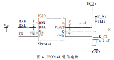
In this paper, the ISO9141-2 protocol is adopted, and the two-way communication chip is selected as the single-ended bus transceiver SI9243A [6] produced by Vishay Siliconix. The chip is designed to meet the requirements of the ISO9141 fault diagnosis system. It has a K-line driver with two-way communication and an L-line receiver that wakes up before data transmission. The communication circuit is shown in Figure 4.
3 fault diagnosis software design
The software of the ABS/ASR/VDC fault diagnosis system consists of two parts, namely, the system self-checking and the on-line detection during the initial self-test and driving.
The fault indicator light is first illuminated during system self-test, and it is also possible to check whether the fault indicator and its line are faulty. If the self-test passes, the fault indicator will go out after about 3 s and the system self-test ends. If there is a fault in the system during the self-test, the fault information is stored in the form of a fault code, and the fault indicator is continuously lit to remind the driver that the ABS/ASR/VDC system has failed. At the same time, the ABS/ASR/VDC system exits, and the normal brake and drive recovery. If the self-test does not detect a fault, the software continues to run.
The initial self-test items mainly include:
(1) Detection of existing fault information in the system and review of some fault information;
(2) Detecting the working conditions of the primary and secondary MCUs through SPI communication;
(3) Checking the main switch of the solenoid valve: opening and closing the main switch of the solenoid valve, judging the working condition of the main switch of the solenoid valve by measuring the value of the power supply voltage VBB of the solenoid valve driving chip;
(4) Checking the function of the solenoid valve: drive the solenoid valve to work and judge whether it works normally;
(5) Checking the static fault of the wheel speed sensor and the excessive speed difference between the wheel speeds at the start of the vehicle;
(6) Check the key software parts to determine whether the program is running normally.
During the work, the ABS/ASR/VDC fault diagnosis system should be used to monitor the working status of the key parts in real time. If the fault is found, it should be dealt with immediately. Online fault diagnosis mainly includes dynamic detection of wheel speed signal, real-time monitoring of solenoid valve and real-time monitoring of main MCU.
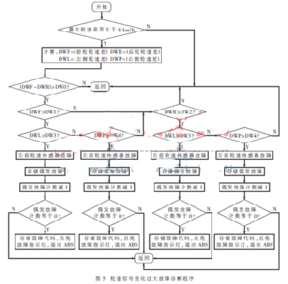
The wheel speed real-time diagnostic program determines whether the wheel speed signal is abnormal by a certain algorithm, and the program logic judgment is as shown in FIG. 5. When the absolute value of the current wheel speed difference and the rear wheel speed difference exceeds the set threshold value, it is determined according to the program logic whether each wheel speed signal has a fault. In the figure, DWF, DWR, DWL, and DWP are the absolute values ​​of the front wheel speed difference, the rear wheel speed difference, the left wheel speed difference, and the right wheel speed difference; DW0 is the front wheel speed difference and the rear wheel. The difference threshold of the wheel speed difference, DW1, DW2, DW3, and DW4 are the threshold values ​​of DWF, DWR, DWL, and DWP, respectively. Considering the road regulations and the actual driving conditions of the car, the thresholds are initially determined through theoretical calculations, and then corrected by experiments. The corrected thresholds are: DW0=2 km/h, DW1=6 km/h, DW2=5 km/h, DW3=7 km/h, DW4=7 km/h.
4 Troubleshooting test verification
During the calibration test of the ABS/ASR/VDC system, when a sudden failure such as a solenoid valve or a wheel speed occurs, the fault indicator light can be illuminated and the ABS/ASR/VDC control is exited. This shows that the designed fault diagnosis system can accurately diagnose and handle the fault diagnosis of solenoid valves and wheel speed sensors. The function of reading, displaying or clearing the fault code can be realized by communication between the ECU and the fault diagnosis instrument.
The designed fault diagnosis system was applied to the self-developed ABS/ASR/VDC integrated system, and the actual road test was carried out. The test results show that the developed fault diagnosis system can detect key component faults in time, store fault codes, exit ABS/ASR/VDC control, and ensure driving safety. The ECU design based on dual MCU architecture enhances the system's fault diagnosis capability, and in some special cases, the auxiliary MCU can replace the main MCU, greatly reducing the failure probability of the ECU.
Plastic Injection Parts is widely applicable drivers, lightings, electronic products' shells, etc.
1. Certification: ISO9001, SGS, CTI, ROHS
|
Product Name
|
Best stainless steel wing nut anchor bolt for construction fastener
|
|
Material
|
stainless steel
|
|
Color
|
nickel white
|
|
Standard
|
DIN GB ISO JIS BA ANSI
|
|
Grade
|
PA-757 765A 757K 750A 0215A
|
|
Used
|
building industry machinery
|


Plastic Injection Parts
Plastic Injection Parts, Plastic Injection electronic, drivers Plastic Injection Parts, lightings Plastic Parts
Shenzhen Jedver Smart Lighting Co., Ltd. , https://www.jederwell.com