PLC common input devices include buttons, travel switches, proximity switches, transfer switches, dialers, various sensors, etc. The output devices include relays, contactors, solenoid valves, and so on. Properly connecting the input and output circuits is a prerequisite for ensuring safe and reliable operation of the PLC.
1. Connection between PLC and main electrical equipment
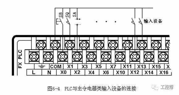
Figure 6-4 shows the wiring diagram of the main electrical input devices such as buttons, travel switches, and transfer switches. The PLC in the figure is a DC sink input, that is, all input points share a common COM, and the COM terminal has a DC24V power supply. For grouped input, you can also perform group connection by referring to the method in Figure 6-4.
2. A rotary encoder is a photoelectric rotary measuring device that converts the measured angular displacement directly into a digital signal (high-speed pulse signal). Therefore, the output pulse signal of the rotary encoder can be directly input to the PLC, and the pulse signal of the PLC is counted by the high-speed counter of the PLC to obtain the measurement result. Different types of rotary encoders have different phase numbers of output pulses. Some rotary encoders output A, B, and Z three-phase pulses, and some have only two phases, A and B. The simplest is phase A.
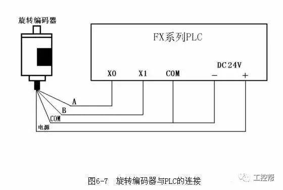
Figure 6-7 shows the connection between the rotary encoder that outputs the two-phase pulse and the FX series PLC. The encoder has 4 leads, 2 of which are pulse output lines, 1 is a COM end line, and 1 is a power line. The power supply of the encoder can be an external power supply, or it can directly use the DC24V power supply of the PLC. The "-" end of the power supply should be connected to the COM end of the encoder, and the "+" should be connected to the power supply end of the encoder. The COM end of the encoder is connected to the COM input terminal of the PLC. The A and B two-phase pulse output lines are directly connected to the input end of the PLC. Pay attention to the response time of the PLC input when connecting. Some rotary encoders also have a shielded wire. When using it, ground the shielded wire.
3. There are many types of sensors, and their output methods are also different. When a two-wire sensor such as a proximity switch or a photoelectric switch is used, the leakage current of the sensor is large, and an erroneous input signal may occur, which may cause a malfunction of the PLC. At this time, the bypass resistor R may be connected in parallel at the input end of the PLC, as shown in the figure. 6-8. When the leakage current is less than lmA, the influence can be ignored.
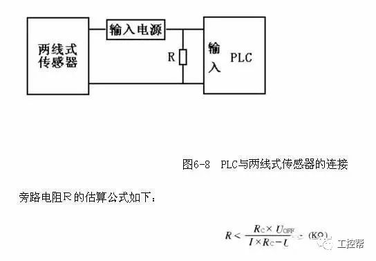
Where: I is the leakage current (mA) of the sensor, UOFF is the upper limit (V) of the PLC input voltage low level, and RC is the input impedance (KΩ) of the PLC. The value of RC varies depending on the input point.
4. If some data in the PLC control system needs to be modified frequently, use the multi-digit DIP switch to connect to the PLC and set the data outside the PLC. Figure 6-5 shows a schematic diagram of a DIP switch. A DIP switch can input 0~9 of a decimal number or 0~F of a hexadecimal number.

Figure 6-5 Schematic diagram of a DIP switch
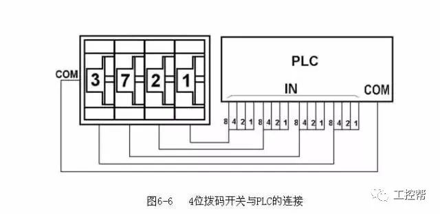
As shown in Figure 6-6, the 4-digit DIP switches are assembled together. Connect the COM terminals of the DIP switches together and connect them to the COM terminals on the PLC input side. The four data lines of each DIP switch are connected to the four input points of the PLC in a certain order. It can be seen from the figure that the use of the DIP switch requires a lot of PLC input points, so it is not very necessary. Generally, this method is not used.
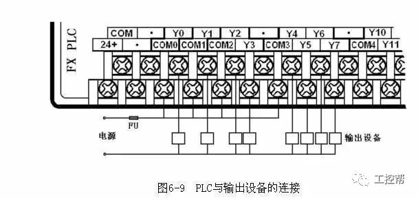
5. When the PLC is connected to the output device, the output points of different groups (different common terminals), the voltage type and level of the corresponding output device (load) can be different, but the output points of the same group (same common terminal), the voltage type It should be the same as the rating. It is necessary to decide whether or not to connect in groups according to the type and level of the output device voltage. As shown in Figure 6-9, the FX2N is used as an example to illustrate how to connect the PLC to the output device. The connection in the figure is the case where the output devices have the same power supply, so the common ends of the groups are connected together, otherwise the packets are connected in groups. Only the Y0-Y7 output points are connected to the output device, and the connection methods of other output points are similar.
6. The output of the PLC is often connected to an inductive output device (inductive load), which causes damage to the internal output components of the PLC in order to suppress the voltage generated when the inductive circuit is disconnected. Therefore, when the PLC is connected to the inductive output device, if it is a DC inductive load, the freewheeling diode should be connected in parallel at both ends; if it is an AC inductive load, the RC absorption circuit should be connected in parallel at both ends. As shown in Figure 6-10.
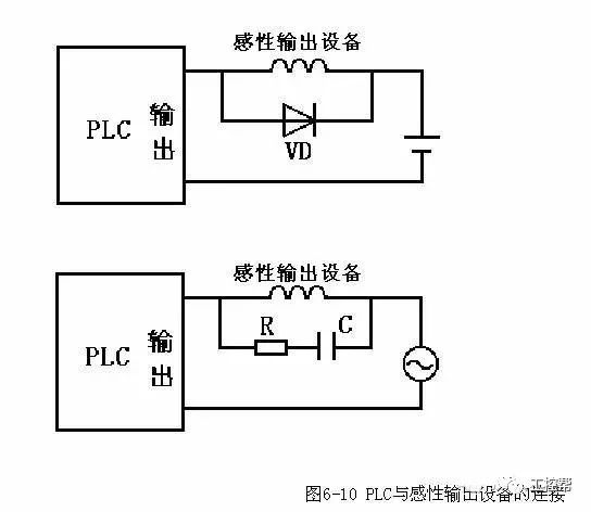
In the figure, the freewheeling diode can be rated at 1A, the rated voltage is greater than 3 times of the power supply voltage; the resistance value can be 50~120Ω, the capacitance value can be 0.1~0.47μF, and the rated voltage of the capacitor should be greater than the peak voltage of the power supply. Pay attention to the polarity of the freewheeling diode when wiring.
7. PLC can directly use the switch output to connect with the seven-segment LED display, but if the PLC controls the multi-bit LED seven-segment display, the required output points are many.

As shown in Figure 6-11, the chip CD4513 with latching, decoding, and driving functions drives the seven-segment display of the common cathode LED. The data input terminals A to D of the two CD4513 share the four output outputs of the PLC. A is the lowest bit and D is the highest bit. LE is the latch enable input. The number of BCDs input to the data input terminal is latched in the on-chip register on the rising edge of the LE signal, and the number is decoded and displayed. If the input is not a decimal number, the display goes out. When LE is high, the number displayed is not affected by the data input signal. Obviously, the number of output points occupied by N displays is P=4+N.
If the PLC uses a relay output module, a pull-up resistor should be connected to each output of the PLC connected to the CD4513 to avoid the input of the CD4513 floating when the contact of the output relay is disconnected. When the state of the PLC output relay changes, its contact may be jittery. Therefore, the data output signal should be sent first. After the signal is stabilized, the data is latched into the CD4513 with the rising edge of the LE signal.
ZGAR Aurora 2500 Puffs
ZGAR electronic cigarette uses high-tech R&D, food grade disposable pod device and high-quality raw material. All package designs are Original IP. Our designer team is from Hong Kong. We have very high requirements for product quality, flavors taste and packaging design. The E-liquid is imported, materials are food grade, and assembly plant is medical-grade dust-free workshops.
Our products include disposable e-cigarettes, rechargeable e-cigarettes, rechargreable disposable vape pen, and various of flavors of cigarette cartridges. From 600puffs to 5000puffs, ZGAR bar Disposable offer high-tech R&D, E-cigarette improves battery capacity, We offer various of flavors and support customization. And printing designs can be customized. We have our own professional team and competitive quotations for any OEM or ODM works.
We supply OEM rechargeable disposable vape pen,OEM disposable electronic cigarette,ODM disposable vape pen,ODM disposable electronic cigarette,OEM/ODM vape pen e-cigarette,OEM/ODM atomizer device.

Aurora 2500 Puffs,ZGAR Aurora 2500 Puffs Pod System Vape,ZGAR Aurora 2500 Puffs Pos Systems Touch Screen,ZGAR Aurora 2500 Puffs Disposable Vape Pod System,2500Puffs Pod Vape System
Zgar International (M) SDN BHD , https://www.zgarecigarette.com