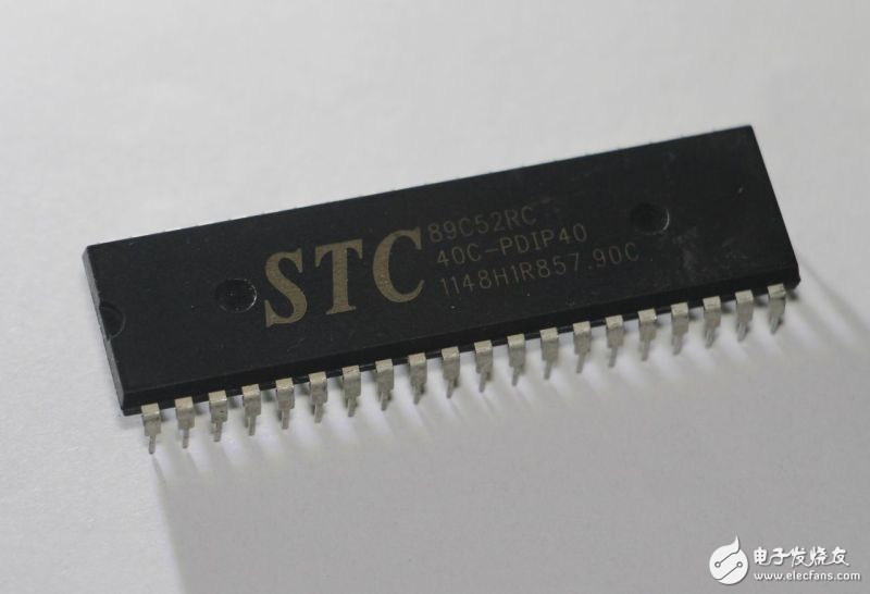
Below we first briefly introduce the specific role of each pin of the 51 MCU, and then focus on the concept, composition of the MCU minimum system and the practical use of each part of the circuit schematic.
According to the pin identification method of the integrated circuit, the gap is turned upwards and counterclockwise, the pin number of the single chip is from 1 to 40, as shown in the figure. The names of the individual pins are also shown in the figure. We don't need to deliberately remember these pin sequences and names. It's fine to check them when needed. If you use more, you will naturally remember them.
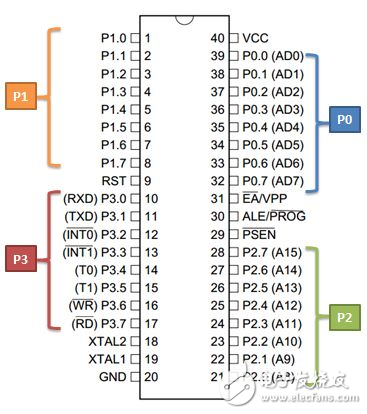
According to the braces in the figure, we refer to the eight pins P0.0~P0.7 as a group of IO ports, called P0, and also P1, P2 and P3. IO port (IO = Input / Output), as the name implies, is the input and output interface, which is the way for the microcontroller to communicate with the outside world. After that, our main learning content is also carried out around the IO port. In addition, these 32 IO ports have some pin names marked in parentheses, called the second function; the second function will be enabled under certain circumstances, and when the second function is not enabled, they only play the IO port. effect. For example, P3.0 and P3.1 are also called RXD and TXD. They have the function of serial port. They can be used to download programs to the MCU, and can also be used for data transmission and reception with the computer, that is, serial communication. In addition to 32 IO ports, there are also eight pins: 29~31 pins are generally not used much, and will not be introduced for the time being; 40-pin VCC, 20-pin GND, 9-pin RST, and 18, 19-foot XTAL1 XTAL2 will soon be explained in detail in the minimum system of the following microcontroller.
What is the minimum system of the MCU? The minimum system refers to the simplest circuit that the MCU can work normally. For 51 MCUs, the minimum system generally includes: power supply, microcontroller, clock circuit and reset circuit. Its circuit diagram is as follows:

Now let's introduce the role of these circuits.
Power circuit: As an electronic device, 51 single-chip microcomputer is of course power supply. It generally uses 5V power supply. We can get 5V power from the familiar USB interface. In the figure, each VCC symbol is commonly connected to the positive pole of the 5V power supply; and all the GND symbols are connected together and connected to the negative pole of the power supply. The reason why the figure is not connected together, but to use multiple VCC and GND symbols, in order to make the circuit diagram look clearer and concise (VCC = Volt Current Condenser, indicating the supply voltage; GND = Ground, grounding meaning, can Simply understood to be connected to the negative pole of the power supply, and we use GND as the reference voltage, the voltage value of GND is always 0V).
Pay special attention to the fact that you must not connect the MCU to an excessively high voltage, or reverse the positive and negative terminals of the power supply, which may burn the MCU and even explode. If the MCU is plugged into the chip socket, since VCC and GND are just in a symmetrical position, the insertion of the power supply will be reversed, so be sure to avoid it.
Here, if you need to know the power supply voltage used by a chip, you can usually check the official chip manual, and the chip manual will be introduced later.
Clock circuit: The circuit connected between the pins XTAL1, XTAL2 and GND is a clock circuit (XTAL = External Crystal Oscillator, which means an external crystal oscillator). The power supply in front is better understood, but what is the clock circuit? What is the use of it? The clock circuit is like a human heart, and it constantly beats every moment, which is crucial for the microcontroller. Just as the heart gives our body constant blood and oxygen, so that the various organs of the body work normally, and the clock circuit is the driving force for the normal operation of all parts of the internal circuit of the microcontroller.
The clock circuit consists of a crystal oscillator and a capacitor. The crystal oscillator is an electronic component made of quartz. When it is energized, its surface will oscillate at a specific frequency. Finally, a clock signal with a very stable frequency can be output through the circuit to drive the microcontroller. Our heart beats tens to hundreds of times per minute, which is too slow for a microcontroller. The crystal frequency in the figure is 12MHz (1MHz=1,000,000Hz). It works normally and oscillates 12,000,000 times per second! In fact, the crystal oscillator of the clock circuit does not have to be 12M, it can be other, but pay attention to the STC89C51 microcontroller. The maximum operating frequency cannot exceed 80M (this can also be found in the chip manual). In fact, we use more of the crystal oscillator of 11.0592M. Why is this strange frequency? I believe the reader will understand when I talk about the serial port later.
The clock circuit also uses two capacitors C2 and C3. If you don't know the capacitor, you can find the relevant information about the common electronic components. I won't introduce it here. These two capacitors usually use ceramic capacitors, and the capacity is generally 30pF.
By the way, if you design your own clock circuit, the connection between the crystal oscillator and the microcontroller should not be too long, which may cause the circuit to not work properly (cannot start).
The time each clock generates an oscillation is called a clock cycle. For the 51 MCU we use, every 12 clock cycles, the MCU performs a one-step operation, which is called a machine cycle (STC also introduces a 1T MCU, every 1 clock). The cycle performs one step). If it is a 12M crystal, the clock cycle is 1/12 us, and the machine cycle is just 1 us.
Everyone should remember the old computer Eniak, which was said in the last century. Eniac can perform 5,000 additions in one second, which was already quite high at the time. But compared with our 51 MCU, it is really awkward. 51 single-chip microcomputer can perform an addition operation (ie, assembly instruction ADD) in one machine cycle. With 12M crystal oscillator, it can perform up to one million addition operations in one second, which is 200 times that of Enniac (regardless of data in register) And the movement between the memory). Seeing here, are you sneaking up for such high-tech things? ^_^
Reset circuit: The part of the circuit connected to the RST pin is the reset circuit, which consists of a resistor and a capacitor. The function of the reset circuit is to send a signal to the MCU just after power-on (for 51 MCU, it is a high level for at least two machine cycles in a row), telling the MCU can start working now. Then the microcontroller starts from the initial state and does not bother to execute a specific program until the power is turned off, or a special situation causes the program to terminate. Under normal circumstances, when the microcontroller is working normally, there should be no termination of the program execution. For this problem, the following will explain the characteristics of the microcontroller program.
The principle of the reset circuit is to charge the capacitor through the resistor when the power is turned on, and let the voltage of the capacitor connected to the RST pin change from 5V to 0V, that is, the high level becomes the low level. The values ​​of the resistors and capacitors can be obtained according to the reference values ​​given in the figure. If you have an understanding of the analog circuit, you can also calculate the value by yourself.
In addition, the EA/VPP pin in the figure is used to access the internal or external program memory selection signal and to provide the programming voltage, which is generally not used. Simply connect to VCC.
When I actually did the experiment, I found that the MCU was not connected to the reset circuit. The two capacitors on the crystal oscillator were omitted and generally worked. But for the sake of safety, you should still connect these if you have the conditions. We need a rigorous scientific attitude.
With the smallest system, the microcontroller can work normally, constantly executing the program we let it execute. The single-chip microcomputer is not afraid of suffering and is not afraid of tired spirit worthy of our study.
Fastener is a kind of mechanical parts used for fastening connection and widely used.A wide variety fasteners of Screw Bolt nut can be found on all kinds of achinery,equipment,vehicles,ships,railways,bridges,building,structures,tools,instruments,meters and supplies.It is characterized by a variety of specifications,performance and use of different and standardization,serialization,generalization of the species is also very high.Therefore,some people have national standard fasteners called standard fasteners or referred to as standard parts.
Fastener
Hardware Fastener,Stainless Steel Fastener,Screw Fastener,Female Fastener,China Fastener
BAODING JIMAOTONG IMPORT AND EXPORT CO., LTD , https://www.chinagroundscrew.com