As the most versatile analog device, the operational amplifier is widely used in signal conversion conditioning, ADC sampling front end, power supply circuit and other occasions. Although the peripheral circuit of the op amp is simple, there are still many places to pay attention to during use.
1, pay attention to whether the input voltage is out of limits
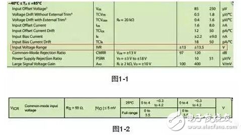
Figure 1-1 is part of the input electrical characteristics of ADI's OP07 datasheet. It can be seen that the input voltage range is ±13.5V at a supply voltage of ±15V. If the input voltage is out of range, the op amp will The work is not normal and there are some unexpected situations.
Some op amps are not labeled with the input voltage range, but the common-mode input voltage range. Figure 1-2 is part of TI's TLC2272 data sheet. Under single-supply +5V, the common-mode input range is 0- 3.5V. In fact, when the op amp is working normally, the input voltages of the non-inverting and inverting terminals are basically the same (virtual and short-circuit), so the "input voltage range" and the "common mode input voltage range" have the same meaning.
2. Do not connect the capacitor directly to the op amp output.
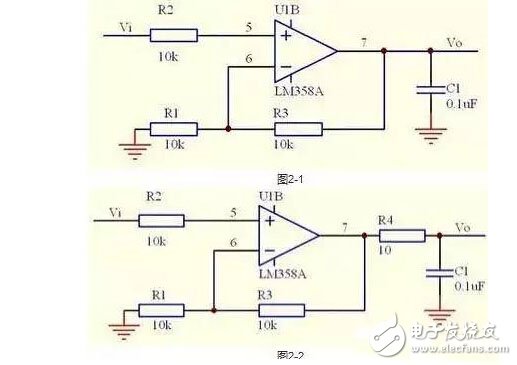
In the DC signal amplifying circuit, sometimes in order to reduce the noise, the decoupling capacitor is directly connected to the op amp output (as shown in Figure 2-1). Although the amplification is a DC signal, it is very unsafe to do so. When there is a step signal input or power-on instant, the output current of the op amp will be relatively large, and the capacitance will change the phase characteristics of the loop, causing the circuit to self-oscillate, which we do not want to see.
The correct decoupling capacitor should form an RC circuit, that is, a resistor is connected in series at the output of the op amp, and then the decoupling capacitor is connected (Figure 2-2). This can greatly reduce the instantaneous current output of the op amp, and will not affect the phase characteristics of the loop, and can avoid oscillation.
3, do not in the amplifier circuit feedback loop and connect capacitor
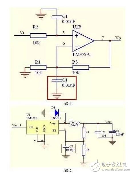
As shown in Figure 3-1, it is also a circuit for DC signal amplification. For decoupling, the capacitor is accidentally connected to the feedback loop. The phase of the feedback signal changes and it is easy to oscillate. Therefore, in the amplifying circuit, the feedback loop cannot be added to any circuit that affects the phase of the signal. This extends to the regulated power supply circuit, as shown in Figure 3-2, and the C3 connected to the feedback pin is wrong. In order to reduce the ripple, C3 can be connected in parallel with R1 to appropriately increase the negative feedback of the ripple and suppress the output ripple.
4, pay attention to the output swing of the op amp
Any op amp can't be an ideal op amp, and the output voltage can't reach the power supply voltage. Generally, MOS-based op amps are rail-to-rail op amps. Under no-load conditions, the output can reach the power supply voltage, but the output will be fixed. The load, the larger the load, the more the output falls. The relative value of the output amplitude of the op amp based on the triode is smaller. Some op amp output amplitudes are 2~6V smaller than the power supply voltage, such as NE5532. Figure 4-1 shows the output characteristics of TI's TLC2272 in +5V power supply. For rail-operated op amps, if the device is used as a preamplifier for ADC sampling (Figure 4-2), a single supply +5V supply, then the input and output become non-linear as the input approaches 0V. The solution is to introduce a negative power supply, such as a -1V negative supply on pin 4, so that the output and input are linear over the entire input range.

5, pay attention to the feedback loop layout
The components of the feedback loop must be close to the op amp, and the PCB trace should be as short as possible. At the same time, try to avoid interference sources such as digital signals and crystal oscillators. If the layout and routing of the feedback loop are unreasonable, noise will be easily introduced, which will lead to self-oscillation.
6, should pay attention to power supply filtering
The power supply filter of the op amp can not be ignored, and the quality of the power supply directly affects the output. Especially for high-speed op amps, the power supply ripple has a great interference on the output of the op amp, and if it is not good, it will become self-oscillation. Therefore, the best op amp filter is to add a 0.1uF decoupling capacitor and a tens of uF tantalum capacitor next to the power supply pin of the op amp, or connect a small inductor or magnetic bead in series, the effect will be better.
li ion 3s battery pack, 9v lowest, 12.6v highest. can be made to reguated stable 9v/10v/11v/12v.
3s battery, 3s lipo, 3s Lipo Battery , 9v Battery ,10.8V Battery Pack,11.1V Rechargeable Battery,12.6V Lithium Battery, 3S Lithium Ion Battery.
9v Battery
9v Battery,10.8V Battery Pack,11.1V Rechargeable Battery,12.6V Lithium Battery
Asarke Industry Co., Limited , https://www.asarke-industry.com