Definition of power supply voltage circuit and classification of voltage regulator circuit

One. Power Conversion Module The so-called power supply voltage refers to the input voltage that is converted through a voltage conversion circuit to achieve boosting or bucking functions for other modules. In the production of smart cars, the input battery voltage is 7.2V. The required voltages for different modules are as follows: 3.3V for the minimum system board, OLED display, and Eagle Eye camera; ±5V for the operational amplifier power supply; 6V for the servo motor; 12V for the drive circuit; and 5V for the CCD and encoder. Below are some detailed explanations about the voltage conversion circuits. Voltage regulator circuits are mainly divided into several categories:
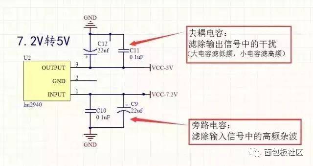
 1. LM2940 to 5V: The LM2940 is a linear regulator circuit that only supports bucking. It has a simple structure and high stability but consumes more power, occupies more space, and has lower filtering efficiency. It requires large input and output filter capacitors.

2. MC34063 to 12V: The MC34063 is a switching DC regulator chip that can be used for both boosting and bucking. This type of circuit has low power consumption, high efficiency, small size, and a wide voltage regulation range. However, its circuit design is more complex, and it has a higher failure rate. The working principle involves the internal switch tube being turned on continuously (the frequency depends on the timing capacitor), with the energy storage inductor and capacitor charging and discharging rapidly to provide energy to the load. The output voltage can be calculated using the formula Uo = 1.25 × (1 + R4/R3).

3. MIC29302 to 6V: The MIC29302 is a linear adjustable regulator that is similar to the MC34063 circuit and can handle high current loads. Its output voltage formula is Uo = 1.242 × (1 + R1/R2). In this case, it provides 6V to power the servo motor.

4. LM2663 to -5V: The LM2663 is a simple negative voltage converter that uses only two external capacitors for operation.

Note: To avoid reverse connection due to manual errors, it’s best to include an anti-reverse protection design in the circuit. 1. Using the unidirectional conductivity of a diode: This method prevents reverse current flow by placing a diode in the circuit.

2. MOSFET-based anti-reverse protection circuit: An NMOS transistor is connected to the negative terminal of the power supply, while a PMOS is connected to the positive terminal. The gate of the NMOS is turned on at a high level, and the PMOS at a low level. Since the on-resistance of NMOS is lower than that of PMOS, it's preferable to use NMOS for better performance.

3. Various anti-reverse interfaces. Two. Motor Drive Circuit The MCU can output a DC signal, but its driving capability is limited. Therefore, the MCU usually uses the driving signal to control a power transistor such as the LR7843, which generates a large current to drive the motor. By adjusting the duty cycle, the average voltage applied to the motor can be controlled, allowing for speed regulation. The motor drive circuit typically uses an N-channel MOSFET to build an H-bridge drive circuit. An H-bridge is a common DC motor control circuit named for its shape resembling the letter "H." The four switches form the vertical legs of the H, and the motor is the horizontal bar. To make the motor run, a pair of diagonal switches must be turned on, and the direction of current determines whether the motor rotates forward or backward.

H-bridge drive principle: In practical drive circuits, switches are usually controlled by a hardware circuit. The motor drive board mainly uses two types of driver chips: the full-bridge driver HIP4082 and the half-bridge driver IR2104. The half-bridge circuit consists of two MOSFETs, while the full-bridge circuit is made up of four MOSFETs. Among them, the IR2104 half-bridge driver chip can drive both high-side and low-side N-channel MOSFETs, providing a large gate drive current and including features like hardware dead time and anti-same-arm conduction.

Additionally, because the driver circuit may generate a large back-EMF current, it's better to isolate the microcontroller from the driver circuit. Common isolation methods include using chips like 74LVC245, 74HC244, or PS2801. These chips are often used as control buses to improve driving capability. Under certain conditions, the output matches the input, allowing one-way signal transmission, meaning the microcontroller signal can be driven to the chip and vice versa.

Customized LED Display

Digit Segment Led Display,Washing Machine Display,Smd Led Display,Bar Segment Led Display

Wuxi Ark Technology Electronic Co.,Ltd. , https://www.arkledcn.com