With the in-depth development of electronic information technology and semiconductor technology, the application of embedded systems is becoming more and more extensive, and more high-performance microprocessors are used in the control field to meet the needs of more and more control applications in various fields. The digital voltage regulation control system based on ARM embedded platform overcomes the drawbacks of traditionally controlling the AC voltage with a knob or a sliding varistor. The system is based on embedded technology, and uses ARM microprocessor to control the conversion of digital-to-analog signals in real time on the embedded platform to control the adjustment of the AC voltage by the sine wave voltage regulator module. In this paper, the functional characteristics of the digital voltage regulation control system are verified by the actual test of the system, and the quantitative test shows that the system can realize the linear adjustment of the AC voltage. The digital voltage regulation control system can be applied to the home, medical and industrial automation fields as an intelligent adjustment device for voltage, and has the characteristics of high adjustment precision, good adjustment linearity, and easy operation.
The voltage regulation control system is used as an intelligent adjustment management device for voltages in home, medical and industrial automation control fields. In the past, the control of the AC voltage was usually implemented by using a sliding or knob-type varistor in the voltage loop. The long-term rotation of the knob caused the adjustment to be insensitive or even ineffective, and the adjustment accuracy was reduced and the error was large. With the rapid development of electronic technology and embedded technology, more and more embedded systems are used in the field of control. It is of great significance to implement digital intelligent control voltage regulation system on embedded platforms. The ARM Cotrex-A8 microprocessor is used to build the hardware control platform, and Linux is used as the embedded operating system. It has strong real-time performance and is easy to develop.
1 ARM digital voltage regulation control system overall design
The hardware design of the ARM digital voltage regulation control system mainly includes the overall design of the hardware, the selection of the processor and the detailed design of the hardware. The main task of the ARM digital voltage regulation control system is to follow the design process of the embedded system, to clarify the functions that the system needs to implement, to divide the hardware modules of the system, determine the processor model after the system hardware structure framework is determined, and set up the development environment. Complete the design goals of this system.
1.1 ARM digital voltage regulation control system structure
The overall hardware design of the system is based on the functional requirements of the system. The research goal of this system is ARM digital voltage regulation control system, which needs to realize the intelligent adjustment of AC voltage through digital signal control. A complete digital voltage control system consists of a core control module, a digital-to-analog signal conversion module, an input and output module, and a sine wave voltage regulator module. The system structure block diagram is shown in Figure 1. The user inputs an instruction from the input/output module to the control module. After receiving the instruction, the control module controls the digital-to-analog conversion module to perform conversion of the digital signal to the analog signal, and the conversion result is output to the sine wave voltage regulating module.
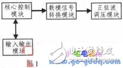
The core control module mainly includes ARM processor, memory, NANDFlash, power management module, etc. All control operations of the digital voltage regulation control system are completed by the processor. The processor is equipped with 512MB of DDR2 memory. The SD card is used to store the Linux system kernel image, file system, drivers and applications. After the system is powered on, the bootloader will boot the operating system and load the application into memory.
The digital-to-analog signal conversion module mainly includes a high-precision digital-to-analog conversion chip. The DAC7311 is selected to realize the conversion of the digital control signal to the analog control signal. The conversion precision is up to 12 bits, and is connected to the processor through the serial synchronization interface.
The input and output module serves as an interactive interface between the user and the system, and mainly includes an LCD touch screen and user buttons for displaying system related information, an application program interface, and a control program.
The sine wave voltage regulating module is connected with the digital-to-analog signal conversion module, and the analog control signal outputted after the digital-to-analog conversion is output to the sine wave voltage regulating module to realize the modulation of the alternating voltage.
1.2 microprocessor selection
The main components of the core control module in this system are embedded microprocessors. In the selection of embedded microprocessors, the performance, technical specifications, power consumption and supported development tools of the microprocessor should be considered in turn. In the PCB design, the layout of the processor and the layout of the layout, the difficulty of wiring, and the cost of the plate making are mainly considered. According to the design goals and functional requirements of the system, and the relevant factors in the design process are integrated, this design selects the ARM embedded microprocessor AM3354 introduced by Texas Instruments. The AM3354 has abundant peripheral resources, superior processing performance, low power consumption, and low cost. The AM3354 is available in two package sizes, 298-pin ZCE package with 0.65 mm solder ball pitch and 324-pin ZCZ package with a solder ball pitch of 0.80 mm. According to the PCB design principle, 324 pin ZCZ package chips are used in this design.
2 ARM digital voltage regulation control system hardware design
The hardware design of the system mainly describes the implementation method of the hardware system. The idea of ​​embedded hardware design is centered on practical applications. The hardware system can be tailored, and functions can be expanded according to actual applications to meet the comprehensive requirements of cost, power consumption and product volume. The basic implementation method of the system is that after the system is powered on, the bootloader reads the Linux operating system and application files into the memory from the SD card and runs the operating system. The system memory uses two 256M MT74H256M8, a total of 512M memory. After the user controls the application to issue an instruction, the processor controls the digital-to-analog conversion module to convert the digital signal to the analog signal by configuring the GPIO interface to simulate the serial synchronization interface.
2.1 core board design
European Socket Connector,Straight Needle European Socket Connector,Waterproof European Socket Connector,Vertical Straight European Socket Connector
Shenzhen Jinyicheng Electronci Technology Co.,Ltd. , https://www.jycconnector.com