In today's global energy shortage environment, energy conservation has become the trend of the times. At the same time, the state also vigorously advocates energy conservation and emission reduction. The end of the 2008 Beijing Olympic Games and the upcoming 2010 Shanghai World Expo will be the same with green energy conservation, which brings huge historical opportunities for the development of China's LED lighting industry. . High-power LED has the advantages of high luminous efficiency, low power consumption, long life, high stability, pure light color, good safety and strong controllability. It is gradually replacing the previous light source and is widely used in full color display. Traffic lights, car lights, background light sources, landscape lighting, special work lighting, etc., have become a new generation of green light sources in the field of lighting. According to the predictions of relevant domestic institutions, the LED lighting market in China will grow rapidly from 4.85 billion yuan in 2007 to 9.81 billion yuan in 2010, driven by the Olympics and the World Expo. Relevant experts believe that China's LED lighting industry will usher in a new development peak around 2010.
statement of problem
In general, the power of high-power LEDs is at least 1W, and currently more common are 1W, 3W, 5W, 8W and 10W. Known as the "green light source", it is moving toward high current (300 mA to 1.4 A), high efficiency (60 to 120 lm/W), and adjustable brightness. However, the luminous intensity of a high-power LED is determined by the current flowing through the LED. If the current is too strong, the LED will be attenuated. If the current is too weak, the LED will be affected. Therefore, the LED driver needs to provide a constant current power supply to ensure high power. The safety of LED use also needs to meet the expected brightness requirements and ensure the consistency of brightness and chromaticity of each LED. Therefore, the power source conventionally used to drive light sources such as light bulbs (tungsten filaments), fluorescent lamps, energy-saving lamps, and sodium lamps is not suitable for directly driving high-power LEDs. Driving high-power LEDs with utility power also needs to address buck, isolation, PFC (power factor correction) and constant current problems, as well as higher conversion efficiency.
At present, there are thousands of special chips on the market for high-power LED constant current driving. There are ADDtek, SITI, SCT, and China Resources Converse (PT) in the world. Supertex, Texas Instruments (TI), Maxim, the country and the United States, Zetex and other well-known manufacturers. Most dedicated chips use hysteresis converter, low voltage input range, boost, buck, PWM control, power switch can be built-in or external, output current can reach 1.5A, built-in overvoltage, undervoltage, open/short And temperature protection circuits, etc.
As shown in Figure 1, the key feature of a hysteretic converter is self-oscillation, which means that the frequency will vary with input voltage, LED current, and the number of LEDs driven. However, such converters often operate in continuous mode, which means that the inductor will never saturate and will not completely drain the current. After the MOSFET is turned off, there is still current to maintain the LED brightness. However, the disadvantage is that the impedance of the detection resistor RCS is different when the duty cycle and the frequency are constantly changing. The current flowing through the RCS is not completely consistent with the actual current of the LED, and the detection data is deviated.
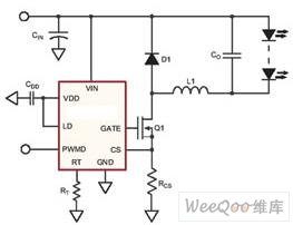
Figure 1 Hysteresis converter
In the field of high-power LED lighting engineering, high-power constant-current driving power of more than 100W is required, and high efficiency and power factor are required. Currently, LED driving power supplies for E27, B22 and GU10 lamps on the market are far from meeting high power. LED lighting engineering field.
Drive design considerations for high power LEDs
From the history of lighting fixtures, there is almost no isolation. The isolation mode design will inevitably affect the driving efficiency of the lamp, and it will not meet the requirements of future energy saving and consumption reduction. Therefore, the LED lighting does not have to be designed in isolation mode.
In terms of the number of series of high power LEDs, the current flowing through the high power LED is no longer limited by the number of high power white LEDs connected in series. In order to meet different lighting brightness requirements, it can be realized by flexibly driving a plurality of high-power LEDs. For the parallel use of high-power white LEDs, this type of circuit still cannot guarantee the uniformity of the brightness of the parallel branch LEDs. However, multiple identical constant current power supplies can be used to drive different parallel branch LEDs in a shunt manner, thus ensuring the consistency of the parallel branch LED properties, thereby solving the problem of uniform brightness of the illumination.
The use of all series connections requires the LED driver to output a higher voltage. When the consistency of the LEDs is large, the voltages distributed across the different LEDs are different, but the current through each LED is the same, and the brightness of the LEDs is the same. If constant-current LED driving is used, when a certain LED is poor in quality, the output current of the driver will remain unchanged, and the remaining LEDs will not be affected. When the quality of a certain LED is broken, the LEDs connected in series will not light up. The solution is to connect a Zener in parallel with each LED. However, the Zener's turn-on voltage is higher than the LED's turn-on voltage, otherwise the LED will not light up. For example, ADDtek's high-power LED protectors A716, AMC7169 and A720 are 350mA, 500mA and 700mA LED protectors. As shown in Figure 2, it is connected in parallel with the high power LED when in use.
The load is disconnected when the power fails. This function is critical in two situations, power down and PWM dimming. As shown in Figure 2, during the power-down of the boost converter, the load is still connected to the input voltage through the inductor and diode. This will continue to produce a small leakage current even if the power supply has failed, greatly reducing the life of the LED. Load disconnection is also important during PWM dimming. During PWM idle, the power supply has failed, but the output capacitor is still connected to the LED, which discharges through the LED until the PWM pulse turns the power back on. When implementing a load disconnect circuit, it is best to place a MOSFET between the LED and the current sense resistor. In the street lighting design, it is generally required to have an automatic shutdown function during the day. A photoresistor can be added in the middle of the circuit. The resistance change during the daytime illumination causes the MOSFET to stop working, and of course the DC/DC can be stopped.
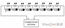
Figure 2 High Power LED Protector
In many cases, it is convenient to adjust the LED current using a low frequency (50 to 200 Hz) PWM method to adjust the brightness by controlling the pulse width. The advantage of this adjustment method is that the spectrum remains the same, and with amplitude adjustment, the spectrum changes as the current flowing through the LED changes. In general, low frequency PWM dimming circuits are more efficient than linear LED dimming circuits. In the design of street lighting, it is generally necessary to reduce the illumination of the street lamp by half at a certain time in the middle of the night to save energy and reduce consumption. A timer can be added in the middle of the circuit to halve the power by outputting a 50% duty cycle.
Waterproof design, divided into outdoor and indoor according to the use environment. Most of the current waterproof power supplies are made of epoxy resin as a waterproof sealing material. The color is mainly black, and of course white and other colors. A few manufacturers have adopted other waterproof filling materials. The important thing is that it can withstand the infiltration of high temperatures, freezing, rain and some corrosive substances.
The 100W LED street light can replace the 250W high pressure sodium lamp or the 300W mercury lamp. 100W LED street light, its output luminous flux is about 6 250lm (after secondary optics design, there will be loss), the lumens when reaching the road is still 6000, and the average illumination of the road can reach 16Lux (rod height 12m). The output luminous flux of the 250W high-pressure sodium lamp is 20 000 lm, but the lumens reaching the road surface is only 7000, and the illumination of the road surface is about 30-40 Lux. Due to the difference in color rendering coefficients, the illumination correction factor of the LED is 2.35 times, and the correction coefficient of the high pressure sodium lamp is 0.94 times. Therefore, after the 100W LED is corrected, the illumination of the ground is 37.6Lux, and the corrected illumination of the high-pressure sodium lamp is 28.2~37.6Lux, which is equivalent. Therefore, the 100W LED street light can replace the 250W high-pressure sodium lamp, and the LED street lamp can save 60% energy.
If the secondary optical design is not carried out, the illumination of the LED is relatively concentrated, so the secondary optical path must be designed so that the light intensity is bat-shaped, and the illumination range can reach 66m.
Main circuit design
The high-power LED lighting constant current driving main circuit adopts excellent BOOST and DC/DC two-stage combination method, which has good dynamic response and steady current characteristics, solves the harmonic pollution problem of the power grid, and makes the high-power LED driving power supply more green. Environmental protection.
BOOST uses an active active power factor correction (APFC) circuit that operates in continuous mode with low harmonic current and switching tube voltage and current stress. The DC/DC uses a half-bridge LLC series resonant converter with a limited number of components. The resonant tank element can be integrated into a single transformer, so only one magnetic component is required. Under all normal load conditions, the primary switch can operate in zero voltage switching (ZVS) conditions, while the secondary diode can operate with zero current switching (ZCS) without reverse recovery losses. Particularly suitable for medium and high output voltage converters, cost-effective, energy-efficient and EMI performance solutions.
The traditional power factor correction circuit has complicated technology, complicated design steps, many required components, large volume and high cost. Therefore, design often tends to trade off between performance and cost. This design uses the IR1150, a new single-cycle AC/DC power factor correction control chip that uses IR's patented single-cycle control (OCC) technology, eliminating the need for analogs required by traditional PFC circuits. Multipliers, input voltage sampling, and a fixed triangular wave oscillator greatly simplify the design of the PFC circuit and reduce the size of the device.
The half-bridge LLC series resonant converter uses Fairchild Semiconductor's highly integrated green FPS power switch FSFR2100. It uses zero voltage switching (ZVS) technology to significantly reduce switching losses in MOSFETs and rectifiers. With this technology, the FPS switch can handle up to 200W without the need for a heat sink, and can handle up to 450W with a heat sink. The FSFR2100 is 10% more efficient than traditional hard-switching converter topologies. It regulates the output with a wide range of input and load changes, while the switching frequency changes relatively little. In addition, it enables zero voltage switching (ZVS) over the entire operating range. Finally, all parasitic components, including the junction capacitance of all semiconductor devices and the leakage inductance and magnetizing inductance of the transformer, are used to implement ZVS.
The main circuit of the illumination constant current driving power supply is shown in Figure 3. The input voltage of the pre-APFC experimental circuit is AC 220V, the rated output is DC 380V, the switching frequency f is 70kHz, and the latter half-bridge LLC series resonant converter. Output voltage range: DC 300 ~ 360V, output rated current 350mA, resonant frequency f0 select 100kHz, transformer turns ratio n = Np / NS = 0.6, power meets 150 ~ 300W output power range. The main circuit is 85V ~ 264VAC → rectification → PFC → 380VDC → DC / DC (isolated) constant current → multiple LEDs in series, APFC can choose power factor correction controller IR1150, L6562 and FAN7527B, half-bridge LLC series resonant converter Use FSFR2100.
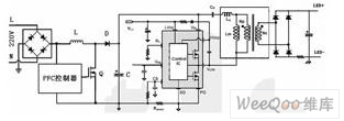
Figure 3 High-power LED lighting constant current drive power supply main circuit
Key technology design
LED lighting drive mode, because the RSET connection directly to the FB terminal will cause RSET power consumption is too large, so the power of the LED constant current drive power supply often put an operational amplifier between the FB feedback terminal and RSET to reduce power consumption. As shown in Figure 4, the op amp takes the voltage on the sampling resistor RSET, combined with other resistors and capacitors to form a complete, high-efficiency high-power LED constant current drive circuit. This will reduce the power consumption of the RSET to an acceptable level while ensuring constant current supply to the LED, so that the voltage across the LED is as large as possible and the current flowing through is as large as possible.
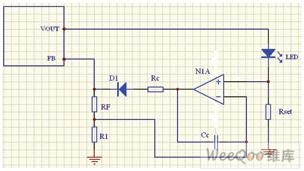
Figure 4 LED constant current drive with low power
The high-power LED constant current driving power supply adopts a hybrid mode of first voltage regulation and then current limiting. In order to meet the load requirements, the voltage needs to be guaranteed within a certain range. The Vf value of the LED is between 3 and 3.6V, then the actual voltage range of the power supply can be determined according to the actual number of LEDs. High-power LED constant current drive as shown in Figure 5, set the maximum set value of the regulator source VSET (such as DC360V), set the steady-state source set value ISET (300mA ~ 1.4A), sample the voltage on RSET If the set value of the steady current source is exceeded, the output voltage will decrease accordingly. According to the number of LEDs connected in series, the output voltage can be reduced to a minimum value (such as DC 300V).
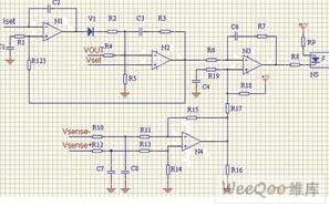
Figure 5 high power LED constant current drive
Compared with the resistor current limiting mode, the switch regulation control mode has higher circuit cost; the control loop can accurately adjust the LED current; the amplitude and low frequency PWM adjustment can be realized; the automatic temperature compensation of the LED characteristic can be realized; the wide input voltage range; No heat sink is required to save cost. For high input voltage and large operating current, other drive schemes will result in very high losses, but this mode can still work efficiently.
Technical indicators
According to the above design scheme, the main technical indicators of high-power LED illumination constant current driving power supply are: input voltage 85~264V; frequency 47~63Hz; output power 100W; output current: 350mA±5% or 700mA±5%; output mode: Multiple 1W high power LED series mode; output voltage range: DC 300 ~ 360V, efficiency ≥ 90%, power factor ≥ 0.99, harmonic ≤ 5%, steady flow accuracy ≤ 5%; with timing, regulation, shutdown function With over-voltage, over-current, short-circuit and over-temperature protection; full sealing, waterproof requirements IP65, dimensions (L × W × H) = 185mm × 70mm × 45mm, weight 1.5kg. Operating temperature -40 ~ +70 ° C, storage temperature -50 ~ +85 ° C, in line with relevant safety regulations, ROHS and electromagnetic compatibility standards, lightning protection design (ICE-61000-4-5 Class 4). Better meet the requirements of lighting engineering.
:
2.1 Multimedia Speaker with USB/SD/AUX fumction
AC power supply
mainly used for Computer ,DVD ,LAPTOP
New fashion design speaker products for markets
2.1 PC Speaker with Aux in
Never again settle for tinny laptop speakers. Boost your home entertainment to a new level with 2.1 channel Bluetooth Speaker system.
Simply plug the 2.1 channel speaker into the 3.5mm jack of your notebook or music player for rich bass and dynamic surround sound.
The 2.1 channel system also supports for FM, Aux in.
Speaker for PC, MP3, MP4, Notebook.2.1 Multimedia Speaker
2.1 Speaker with USB,2.1 Speaker with SD,2.1 Speaker with Aux,2.1 Multimedia Speaker
winkey international technology co., limited , http://www.yqspeaker.com