As a globally recognized LAN authority, the standards established by the IEEE 802 Working Group have dominated the LAN in the past two decades. These protocols include the 802.3 Ethernet protocol, the 802.5 Token Ring protocol, and the 802.3z 100BASE-T Fast Ethernet protocol. In 1997, after seven years of work, the IEEE released the 802.11 protocol, which is the first internationally recognized protocol in the field of wireless LAN.
In September 1999, they proposed the 802.11b "High Rate" protocol to supplement the 802.11 protocol. 802.11b adds two new network throughput rates of 5.5 Mbps and 11 Mbps at 802.11 1 Mbps and 2 Mbps. Later, it evolved to 54Mbps for 802.11g, up to 108Mbps for 802.11n today.
With 802.11b, mobile users can achieve the same performance, network throughput, and availability as Ethernet. This standards-based technology allows administrators to choose the right LAN technology to build their own network to meet the needs of their business users and other users.
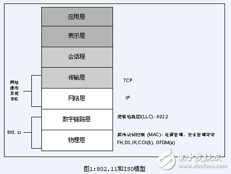
Like other IEEE 802 standards, the 802.11 protocol works primarily on the lowest two layers of the ISO protocol, the physical layer and the digital link layer (see Figure 1). Any LAN application, network operating system or something like TCP/IP or Novell NetWare can run on 802.11 protocol as if they were running on 802.3 Ethernet.
The basic structure, features, and services of 802.11b are defined in the 802.11 standard. The 802.11b protocol mainly includes some changes in the physical layer, adding the characteristics of high-speed digital transmission and the stability of the connection.
802.11 working style
802.11 defines two types of devices, one is a wireless station, usually formed by a PC machine plus a wireless network interface card, and the other is called a wireless access point (AP), its role It provides a bridge between wireless and wired networks. A wireless access point usually consists of a wireless output port and a wired network interface (802.3 interface), and the bridge software complies with the 802.1d bridge protocol. An access point is like a wireless base station of a wireless network that aggregates multiple wireless access stations onto a wired network. The wireless terminal can be an 802.11 PCMCIA card, a PCI interface, an ISA interface, or an embedded device (eg, an 802.11 handset) on a non-computer terminal.
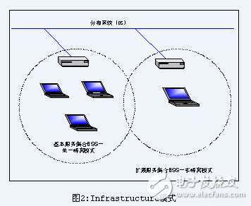
802.11 defines two modes: infrastructure mode and ad hoc mode. In infrastructure mode (see Figure 2), the wireless network has at least one wireless access point connected to the wired network, and also includes a series of wireless terminal stations. This configuration becomes a BSS (Basic Service Set). An ESS Extended Service Set is a single subnet consisting of two or more BSSs. Since many wireless users need to access devices or services (file servers, printers, Internet links) on the wired network, they will adopt this infrastructure mode.
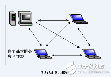
Ad hoc mode (also known as peer-to-peer mode or IBSS Independent Basic Service Set)
802.11 physical layer
The three physical layers originally defined in 802.11 include two diffusion spectrum technologies and one infrared propagation specification. The wireless transmission channel is defined in the 2.4 GHz ISM band, which is used in various international wireless management organizations, such as the United States. ETSI in Europe and MKK in Japan are all non-registered frequency bands. This way, 802.11 client devices do not require any wireless licenses. Diffusion spectrum technology guarantees the availability and reliable throughput of 802.11 devices in this band. This technology also guarantees that it does not interact with other devices using the same frequency band.
Initially, the transmission rate defined by the 802.11 wireless standard is 1 Mbps and 2 Mbps. FHSS (frequency hopping spread spectrum) and DSSS (direct sequence spread spectrum) techniques can be used. It should be noted that the FHSS and DHSS technologies are completely different in operation mechanism. Therefore, devices using these two technologies have no interoperability.
Using FHSS technology, the 2.4G channel is divided into 75 1MHz sub-channels, and the receiver and the sender negotiate a frequency modulation mode, and the data is transmitted on each sub-channel according to this sequence, each time session on the 802.11 network. A different frequency hopping mode may be adopted. The frequency hopping mode is mainly used to avoid the same sub-bands being used by both transmitting ends.
The FHSS technology adopts a relatively simple method, which also limits the maximum transmission speed that can be obtained by no more than 2 Mbps. This limitation is mainly determined by the sub-channels specified by the FCC to be no less than 1 MHz. This limitation makes FHSS must frequently hop across the entire 2.4G band, resulting in a lot of hopping overhead.
Contrary to FHSS, direct sequence spread spectrum technology divides the bandwidth of 2.4Ghz into 14 22MHz channels, and adjacent channels overlap each other. In 14 frequency bands, only 3 bands are not covered by each other. Data is transmitted from one of these 14 bands without the need for a jump between channels. To compensate for the noise overhead in a particular frequency band, a technique called "chipping" is used to solve this problem. The data in the data transmitted in each 22MHz channel is converted into a Chips data with redundancy check, which is transmitted along with the real data to provide error checking and error correction. Due to the use of this technology, most of the data that transmits errors can also be corrected without retransmission, which increases the throughput of the network.
802.11b enhanced physical layer
The biggest contribution of 802.11b in the WLAN protocol is that it adds two new speeds to the physical layer of the 802.11 protocol: 5.5 Mbps and 11 Mbps. In order to achieve this goal, DSSS was selected as the only physical layer transmission technology of the standard, because FHSS can no longer improve the speed without violating the FCC principle. This decision allowed 802.11b to interoperate with 1Mbps and 2M 802.11bps DSSS systems, but not with 1Mbps and 2Mbps FHSS systems.
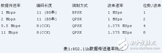
The original 802.11 DSSS standard uses an 11-bit chipping-Barker sequence to encode and transmit data. Each 11-bit chipping represents a one-bit digital signal of 1 or 0. This sequence is converted into a waveform (called a Symbol). And then spread in the air. These Symbols are transmitted at a rate of 1 MSps (1M symbols per second). The transmission mechanism is called BPSK (Binary Phase ShifTIng Keying). In the 2Mbps transmission rate, a more complicated transmission method called QPSK (Quandrature) is used. Phase ShifTIng Keying), the data transmission rate in QPSK is twice that of BPSK, which increases the bandwidth of wireless transmission.
In the 802.11b standard, a more advanced coding technique has been adopted. In this coding technique, the original 11-bit Barker sequence technology is abandoned, and CCK (Complementary Code Keying) technology is adopted. There is a collection of 64 8-bit codes, and the data in this set has special mathematical properties that allow them to be correctly distinguished from each other after interference or due to multi-concept problems caused by reflection. 5.5 Mbps uses a CCK string to carry 4-bit digital information, while a 11 Mbps rate uses a CCK string to carry 8-bit digital information. Both rate transmissions utilize QPSK as a means of modulation, but the modulation rate of the signal is 1.375 MSps. This is also the mechanism by which 802.11b gets high speed. These data are listed in Table 1.
To support better transmission rates in noisy environments, 802.11b uses dynamic rate adjustment technology to allow users to automatically use different connection speeds in different environments to complement the adverse effects of the environment. In the ideal state, the user runs at full speed of 11M. However, when the user moves out of the ideal 11M rate transmission position or distance, or is potentially interfered, the speed is automatically reduced to 5.5Mbps, 2Mbps, 1Mbps. . Similarly, when the user returns to the ideal environment, the connection speed will increase in the reverse direction up to 11 Mbps. The rate adjustment mechanism is implemented automatically at the physical layer without any impact on users and other upper layer protocols.
802.11 digital link layer
The data link layer of 802.11 is composed of two layers, a logical link layer LLC (Logic Link Control) and a media control layer MAC (Media Access Control). 802.11 uses the same layer of LLC as 802.2 and a 48-bit MAC address in the 802 protocol, which makes bridging between wireless and wired very convenient. But the MAC address is only unique to the wireless LAN.
The MAC of 802.11 is very similar to the MAC of 802.3 protocol. It supports multiple users to share resources on a shared media. The sender can make the network available before sending data. In the 802.3 protocol, the adjustment is done by a protocol called CSMA/CD (Carrier Sense MulTIple Access with Collision DetecTIon), which solves the problem of how each workstation on the Ethernet transmits over the cable. It detects and avoids collisions on the network when two or more network devices need to transmit data. In the 802.11 WLAN protocol, there is a problem with the detection of collisions. This problem is called the "Near/Far" phenomenon. This is because the device must be able to transmit data signals while receiving data signals, and this is in the wireless system. It is impossible to do it.
In view of this difference, some adjustments have been made to CSMA/CD in 802.11, using the new protocol CSMA/CA (Carrier Sense Multiple Access with Collision Avoidance) or DCF (Distributed Coordination Function). CSMA/CA uses the ACK signal to avoid collisions. That is to say, only when the client receives the ACK signal returned on the network, it confirms that the sent data has arrived correctly.
The workflow of the CSMA/CA protocol is: a workstation wants to transmit data in a wireless network. If it does not detect that data is being transmitted in the network, it waits for a period of time, and then randomly selects a time slice to continue the detection, if the wireless network is still in the network. If there is no activity, the data will be sent out. The workstation at the receiving end sends back an ACK datagram if it receives the complete data sent by the sender. If the ACK datagram is received by the receiver, the data transmission process is completed. If the sender does not receive the ACK datagram, then The transmitted data is not completely received, or the transmission of the ACK signal fails. Regardless of the phenomenon, the datagram is retransmitted after waiting for a period of time at the transmitting end.
In this way, CSMA/CA provides wireless shared access. This explicit ACK mechanism is very effective in dealing with wireless problems. However, for 802.11 or 802.3, this approach adds an extra burden, so 802.11 networks and similar Ethernet networks are always inferior in performance.
Another wireless MAC layer problem is the "hidden node" problem. The two opposite workstations are connected using a central access point, both of which are able to "listen" to the presence of the central access point, while the other party may not be aware of the existence of the other party due to obstacles or distance. To solve this problem, 802.11 introduces a new Send/Clear to Send (RTS/CTS) option on the MAC layer. When this option is turned on, a transmitting station transmits an RTS signal, and then waits for the access point to return the RTS signal. Since all the stations in the network can "listen" to the signals sent by the access point, CTS can stop them from transmitting data, so that the sender can send data and accept ACK signals without causing data collision. Indirectly solved the "hidden node" problem. Since RTS/CTS needs to occupy network resources and add extra network load, it is generally only used on those big datagrams (retransmission of big datagrams will be expensive).
Finally, the 802.11 MAC sublayer provides two other robust features, CRC checksum packet fragmentation. In the 802.11 protocol, each datagram transmitted in the wireless network is tagged with a check digit to ensure that it does not have an error during transmission. This is verified by the upper layer TCP/IP protocol in Ethernet. It is different. The function of packet fragmentation allows large datagrams to be divided into smaller parts for batch transfer at the time of transmission. This is a very useful feature when the network is very crowded or has interference (big datagrams are very vulnerable to transmission in this environment). This technology greatly reduces the probability that datagrams will be retransmitted in many cases, thereby improving the overall performance of the wireless network. The MAC sublayer is responsible for reassembling the received fragmented big datagrams, which is completely transparent to the fragmentation process of the upper layer protocol.
Joint structure, cellular structure and roaming
The MAC sublayer of 802.11 is responsible for resolving the connection between the client workstation and the access point. When an 802.11 client enters the coverage of one or more access points, it automatically selects an access point to connect based on the strength of the signal and the packet error rate (this process is also called joining a basic service set). BSS). Once accepted by an access point, the client switches the channel that receives the received signal to the frequency band of the access point. In the subsequent time, the client periodically polls all frequency bands to detect if other access points can provide higher performance services. If it detects it, it will negotiate with the new access point and then switch the channel to the service channel of the new access point. (See Figure 4)
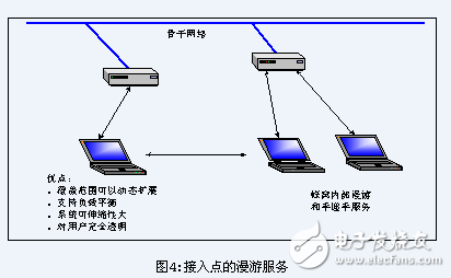
This renegotiation usually occurs when the wireless workstation moves out of the service range of the access point to which it was originally connected, after the signal is attenuated. Other situations also occur with changes in the signal caused by the building or simply due to congestion in the original access point. In the case of congestion, this renegotiation implements a "load balancing" function that will maximize utilization of the entire wireless network.
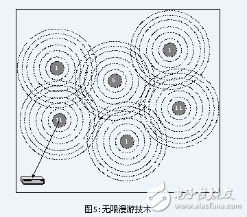
This dynamic negotiation connection is handled in such a way that network administrators can extend the coverage of the wireless network by arranging multiple access points with overlapping coverage in these areas. IT administrators must be aware that the coverage between 802.11 DSSS channels must comply with certain specifications, and the adjacent channels cannot overlap each other (see Figure 5). In the previous 802.11 DSSS, there was a mutual coverage. Of the 14 channels, only three of the 14 channels are completely uncovered, and it is most appropriate to use these channels as multi-cellular coverage. If the coverage of the two access points affect each other and they use bands that cover each other, this will cause them to interfere with each other during signal transmission, thereby reducing the performance and efficiency of their respective networks.
Time-based data support
Time-related data such as voice and video is supported at the MAC layer of 802.11, which is implemented by a function called PCF (Point Coordination Function). Unlike DCF, which gives all control to the client workstation, the access point has full control over the transmission medium in the PCF mode of operation. If PCF is turned on in a basic service set, the control time is shared by PCF and DCF (CDMA/CA). When in PCF mode, the access point will query the client one by one to obtain data. The client being inquired has no right to send data, and the client can only re-acquire data at the point of access when it is asked. Since the time and order of processing each client by the PCF is fixed, a fixed delay can be guaranteed. One disadvantage of PCF is that its scalability is not very good. After the network scale becomes larger, the number of clients it polls increases, resulting in a sharp drop in network efficiency.
Power management
The 802.11 HR MAC layer supports a power saving mode to extend the battery life of handheld devices. This standard is up to two power utilization modes, called CAM (Continuous Aware Mode) and PSPM (Power Save Polling Mode). In the former mode, the signal is always present and consumes power. In the latter mode, the special signal of the access point regulates the client's device in a "sleep" and "wake-up" state. The client's device will periodically enter the "wake-up" state to accept the "beacon" signal from the access point. This signal contains information about whether other clients need to perform data transfer activities with the local machine. If so, the client After accepting "beacon", the terminal enters the "wake up" state to accept the data, and then enters the "sleep" state.
Safe and healthy
802.11 provides the access control function and encryption mechanism of the MAC layer (the second layer of OSI). This encryption mechanism is called WEP (Wired Equivalent Privacy), which makes the wireless network have the same security as the wired network. For access control, the ESSID (also known as the WLAN service area number) can be encoded in any access point according to its own requirements. This number needs to be set in the wireless client device that needs to be accessed. In addition, an access control list is also defined in the access point to restrict access to the access point, and only clients having a MAC address listed in the access control list can access the access point.
For data encryption, the standard provides encryption using the 40-bit RC4 PRNG public key algorithm in RSA data encryption. All data sent and received at the terminal and access point is encrypted using a key. In addition, when encryption is used, the access point will issue an encrypted origination datagram to all clients within the connection range. The client must send back a datagram that was processed with the correct key before it can get a connection to the network.
In addition to working at Layer 2, 802.11 HR wireless networks can also support secure access control standards for other 802 LANs (such as registration behavior of network operating systems) or encryption (IPSec and other application layer encryption). These high-level encryption technologies enable end-to-end secure networks that include both wireless and wired networks.
Digital Air Fryer,Best Digital Air Fryer,Digital Oil Less Fryer,Electric Digital Air Fryer
Ningbo ATAP Electric Appliance Co.,Ltd , https://www.atap-airfryer.com