1 SAE J1939 Protocol Overview The SAE J1939 standard is a CAN bus-based vehicle network serial communication and control protocol issued by the Society of Automotive Engineers (SAE). It uses multiplexing technology for sensors, actuators and controllers on the vehicle. It provides standardized high-speed network connection based on CAN bus, realizes high-speed data sharing between vehicle electronic devices, effectively reduces the number of electronic harnesses, and improves the flexibility, reliability, maintainability and standardization of vehicle electronic control systems.
1.1 Introduction to the SAE J1939 Protocol The J1939 protocol includes 12 sub-standards. This paper mainly deals with two sub-standards of vehicle application layer and application layer diagnosis. The Vehicle Application Layer Standard (SAEJl939/71) specifies the format of vehicle control control parameters, including parameter range, resolution, type and refresh rate, meaning of each field of the data field; application layer diagnostic sub-standard (SAEJl939/73) is mainly for emissions The requirements specify 12 diagnostic results information.
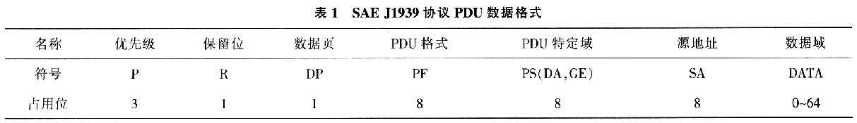
1.2 Protocol Data Unit The SAE J1939 application layer protocol uses protocol data unit PDUs to convey information. The PDU consists of priority P, reserved bit R, data page DP, PDU format PF, PDU specific domain PS (can be used as destination address, group extension or Dedicated), source address SA and data field 7 are composed, as shown in Table 1. Each PDU is equivalent to one frame in the CAN protocol, which will be packet encapsulated in one or more CAN data frames for transmission to other network devices over the physical medium.
This article refers to the address: http://
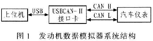
2 Overall scheme design In the development process, by using the USBCAN-II interface card library port function, the communication between the host computer and the lower computer is realized by the CAN bus. The engine bus data simulator sends data to the bus meter through the USBCAN-II intelligent interface and displays it in real time to achieve the purpose of the test instrument. The system structure is shown in Figure 1.
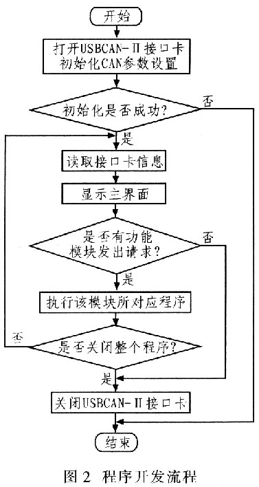
The system mainly includes six major functional modules, which are engine parameter message sending module, engine fault message sending module, CAN frame information display module, virtual instrument module, real-time parameter curve module and instrument test module. The system software is developed in C# environment and runs on Windows platform. The overall process of system development is: first realize the communication with the USBCAN-II interface card. After the connection is successful, select the functions that need to be implemented in the main interface, and then perform the operations of the relevant modules. Turn off the USBCAN-II interface card while the program is closed. The program development process is shown in Figure 2.
3 Engine bus data simulation system design Here we focus on SAE J1939-7l definition of engine parameters and SAE J1939-73 definition of fault diagnosis information, clarify the format of the engine to send messages and the meaning of the data, and design the system modules.
3.1 Engine parameter message transmission module This module is a set of data for analog field test. According to SAEJ1939 CAN communication specification for Euro III engine suitable for BOSCH high pressure common rail system, frame ID and data byte representing engine parameters are used. The location corresponds to the update rate specified in the message. The engine parameters are continuously sent to the bus network. The module has a single transmission and sends two modes according to the update rate specified by the J1939 protocol. Engine parameters include engine speed, vehicle travel speed, oil pressure, water temperature, and the like.
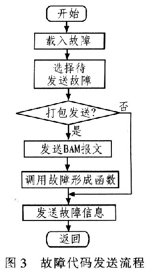
3.2 Engine fault message sending module This module adds fault diagnosis function to the bus meter, that is, the bus meter can display the fault type of the engine in real time by means of the liquid crystal display. The program flow of the module is shown in Figure 3. The calibrated faults in turn specify the fault path, fault details, number, SPN and FMI.
3.3 Virtual instrument module The virtual instrument mainly displays the engine's engine speed, vehicle speed, oil pressure, water temperature, voltage and other important parameters on the virtual instrument panel, which more intuitively displays the corresponding data and simulates the actual running state of the driving instrument. Using Dundas Gauge for Dundas Software. NET for the visual development of virtual instruments, Dundas software platform fully supports Visual Studio 2005 features, including smart tags, advanced data binding. The Dundas Meter Wizard provides a rich library of materials that users can use to design gauge shapes and data indications for a variety of applications. Users only need to write code in the application to the part of the instrument that needs to be dynamically changed and responsive to implement the function of the virtual instrument.
3.4 CAN frame information display module This module is implemented by calling a listview control. The column elements are time, frame ID, P, R, DP, PF, PS, SA, frame format, frame type, data length, data. , transmission direction, time identification, the first few CAN. Among them, P, R, DP. PF, PS, SA are obtained by the frame ID resolution function, and others are derived from the parameters of the interface function library.
Taking the engine speed as an example, the CAN frame information analysis (actual parameter = original number × resolution + offset) is given. Message name: Electronic Engine Controller #1 (EEC1), SPN: 190, PGN: 61 444, ID: OxCF00, source address: engine (receiving address: ABS (0x0B), meter (0x17), update rate: 10 ms, Position: 4 to 5 bytes, resolution: 0.125 r/min, 0 offset, data range: 0 to 8 031_875 r/min. To send a speed of 3 000 r/min, the fourth data is sent. The 5 bytes should be: 3 000 / 0.125 = 24 000 (0xC051)). The sending PDU code is: 0CFD0400 XX XX XX C0 5D XX XX XX (XX stands for arbitrary data).
3.5 Real-time parametric curve module The real-time parametric curve module utilizes Dundas Chart for. NET displays the engine speed, lubricant pressure and other parameters in a dynamic curve, and can output and save the display data, and also provide historical data playback function. It includes four curves of speed, oil pressure, water temperature and voltage. The module and the virtual instrument module jointly realize dynamic and intuitive display of engine parameters, which is convenient for experimental debugging.
3.6 Instrument Test Module This module compares the speed of the pointer of the virtual instrument with the development instrument and tests the stepper motor drive effect of the development instrument. By selecting the dial to be tested, setting the maximum value of the transmitted data, and the number of tests, the virtual instrument can be cycled within the selected range to be compared with the instrument to be tested. The instrument test module can provide a reference for the development of the instrument more intuitively.
4 system verification
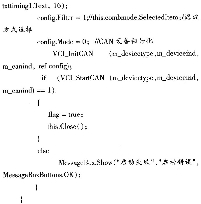
4.1 Connecting the USB-t0-CAN device The design of the USB-t0-CAN system is based on the connection of USB-to-CAN devices. First select the device index number, call the function, and open the device. Select the first few CANs to initialize the CAN device. Open the device interface as shown in Figure 4.

The relevant code is as follows: 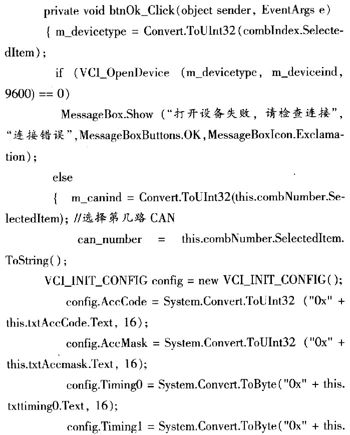
4.2 Virtual instrument and CAN frame information display module After verifying that the engine parameter message is sent, after analysis, the CAN frame information and the virtual instrument real-time display status are as shown in Fig. 5.

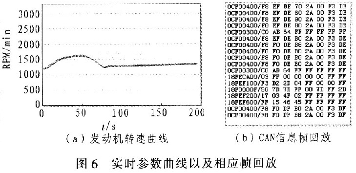
4.3 Real-time parameter curve module verifies that the data displayed by the real-time curve tool is synchronized with the virtual instrument. When the value of the virtual instrument changes, the chart control also adds the same data point to the chart with time as the abscissa, thus generating a continuous Curve. After completing a test process, the data can be saved and output as a standard XML format file. The module also provides historical data playback to redraw a saved XML file into a data curve. The working process is shown in Figure 6.
5 Conclusion Based on the research of CAN bus protocol, this paper completed the development of engine bus data simulator based on SAE J1939 protocol in C# programming environment. The system is connected with the bus instrument to be developed, and can simulate the data output of various working conditions of the engine. Once an engine parameter is selected, the engine parameters are continuously sent to the bus instrument to be developed at the update rate specified in the message.
This software can partially replace the real engine, randomly test the engine's various working conditions, and has strong flexibility. The selection range is wider than the actual engine. The system can assist in hardware development such as bus instrumentation, simplifying the bus instrument test process.
Wood Grain, Unique and Compact Design: This Aroma Diffuser is coated with wood grain, which makes it look very natural and primitive. With compact and portable design, the cap of the aroma diffuser is easy to take off, you won`t bother to unscrew the cap with great force when your hands is wet. Just gently take off the cap, add water and essential oil, enjoy high-quality life.
Portable with Adjustable Mist Output: Essential Oil Diffuser hold up to 200ml of water, not too big, not too small. It produce up to 35-70ml of moisture per hour. It can run up to 5.5 hours of continuous output in low mist. Automatic power off when water used up, which ensures safety. A long press to switch between high and low mist to extend the duration of misting. (One beep for high mist mode, two beeps for low mist mode)
7 Color LED Lights. 7 colors rotating through / Fixed one color steady on / Lights off. Each color is adjustable between bright and dim. A perfect nightlight for a kid's bedroom and soft light creates romantic atmosphere which helps you escape the hustle and bustle of modern life.
4 Timer Settings and Auto Shut off: 4 time setting modes: 1H/ 3H/ 6H/ ON/OFF. Diffuser automatically powers off when water level is too low.
Mulfunctional: Aromatherapy Diffuser adopts ultrasonic technology, this diffuser is extremely quiet when working. It gives out ultra fine and smooth mist which can soften and moisten dry and chapped skin in winter. It also helps you breathe better when your are sleeping with air conditioner on.
Home Humidifier,House Humidifier,Home Evaporative Humidifier,Home Warm Mist Humidifier
Shenzhen Hygea Technology Co.,Ltd , http://www.hygeaaromadiffuser.com