Siemens SIMATIC S7 series serial communication modules, such as CP340, CP341, CP440-1, CP441-1/2, CPU313C/314C-2PtP, and ET200S 1SI 3964/ASCII, support the ASCII driver protocol. These modules are widely used for point-to-point communication with instruments, devices, and systems that use third-party ASCII protocols. They offer simple application, flexibility, and ease of use.
This section provides a practical example of using the ASCII driver protocol to implement polling communication between multiple Siemens serial communication modules (CP340/CP341). The specific implementation method and polling principle have broad guiding value and can serve as a reference for serial communication between Siemens modules and other devices or systems that support ASCII protocols.
System Composition
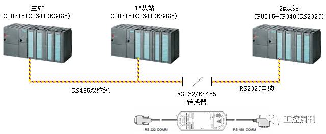
As shown in the figure below, the system consists of three SIMATIC S7-300 stations, one of which acts as the master station for serial communication. It polls data from two slave stations using the ASCII driver protocol. The master station and the first slave station are equipped with a CP341 module (6ES7341-1CH01-0AE0) with an RS422/485 interface, while the second slave station uses a CP340 module (6ES7340-1AH02-0AE0) with an RS232C interface. To connect these modules to a network, a Siemens PC/PPI cable (6ES7901-3CB30-0XA0) is used to convert the RS232C interface of the second slave station to an RS485 interface.
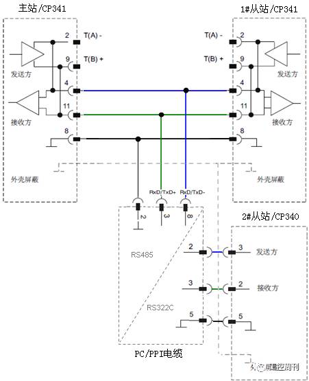
2. Cable and Hardware Connection
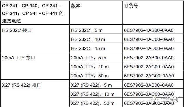
Detailed hardware connection is shown below:
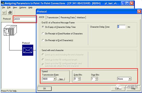
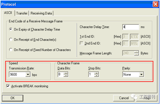
3. Configuration of Master Station
• CP341 module start address: 256, ASCII protocol mode;
• End of message frame standard: character delay time 4ms;
• Baud rate: 9600bps, 8 data bits, 1 stop bit, no parity;
• Interface type: RS485 half-duplex;
• Others use default values.

4. Configuring the Slave
The parameter settings for the slave CP341/CP340 modules are identical to those of the master station. Special attention should be given to ensuring that the baud rate, data bits, stop bits, and parity settings match those of the master station.
5. Polling Principle
Unlike the MODBUS protocol, where each slave has a unique device ID, the ASCII protocol does not include a unique slave address. Therefore, the master must manually identify which station the data frame is intended for and whether it needs to respond. Multi-site polling using the ASCII protocol requires the master to send a specific instruction identifier so that the slave can determine if it is the target station.
When implementing multi-site polling via the ASCII protocol, the following aspects should be considered:
• Basic mode: the master actively requests, and the slave responds accordingly;
• Data frame: the site identifier should be included in the sending or response frame;
• Implementation method: timed polling, starting the next job immediately after completion, or with a delay;
• Verification and error handling: CRC, wait, discard, retry, etc.
6. Polling Mechanism
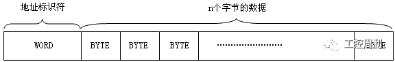
1. Data Frame Format
To distinguish between the first and second slave stations, an address identification character is added to the message frame. The master polls different slaves by transmitting frames with different address identifiers. The slave checks the address characters to determine if the message is intended for itself and responds accordingly. The response frame also contains its own address identifier, allowing the master to identify which slave sent the data. The character frame format is as follows:
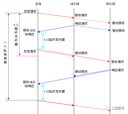
2. Timing Diagram
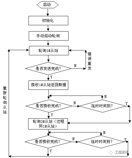
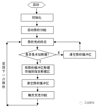
3. Flow Chart
Initialization Process
The initialization process primarily applies to the master station. During this phase, the CP module is configured, the polling counter is initialized, the receive buffer is reset, and the transmit data frame is generated based on the polling counter.
Main Station Polling Process
After system initialization, the first polling operation is manually initiated. In this example, the first slave is polled first. After sending a query request to the first slave, the master waits for a response. If the data from the first slave is received within the specified delay time, the query is sent to the second slave, and the master waits for its response. If the data is received within the allowed time, a complete poll is completed, and a new round begins automatically. If no data is received within the delay time, the station is skipped, and the next station is polled.
Slave Response Process
The slave responds to the master's request. Upon receiving data on the network, it determines if it is intended for itself. If so, the data is stored in the designated area, and the corresponding response is sent back to the master. If not, the received data is simply discarded without any response.
7. Master Program
1. Initialization
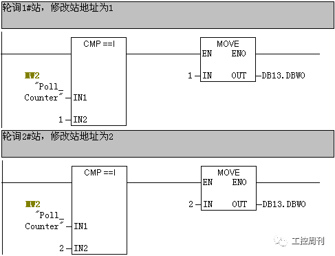
To enable polling of multiple slaves, the program constructs a polling counter that modifies the station address identifier in the transmitted data frame. Here, MW2 is defined as the polling counter. The program starts by initializing the counter, and by default, the first slave is polled, assigning the value 1 to MW2.
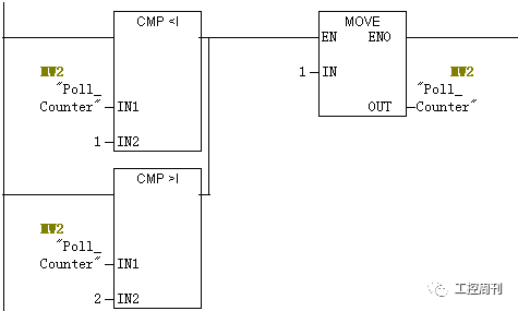
During program execution, the polling counter is modified, and the address identifier word in the transmitted data block is updated accordingly to complete the polling of the responding slave. For instance, DB13 is used as the transmission data block, with DB13.DBW0 serving as the address identifier word.
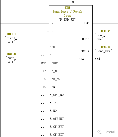
2. Start Sending
After initialization, the send function can be triggered. In this case, the first transmission is done manually by setting the manual start flag M30.1, and calling FB8 P_SND_RK to send data to the slave. Once the first transmission is complete, the automatic polling flag M30.0 is automatically set to enable continuous polling.
After FB8 is started, status information is returned to determine if the transmission was successful. If an error occurs, the transmission is retried.
Upon completion of the send, the receive job is started, and the slave's return data is prepared for reception. A timeout timer T11 is also started. If no data is received before the timer expires, the system waits for the next call and proceeds to the next station.
3. Receive Slave Data Return
Once the transmission is complete, the receive job is initiated, and the received data is placed into the receive buffer, which is located in DB14.
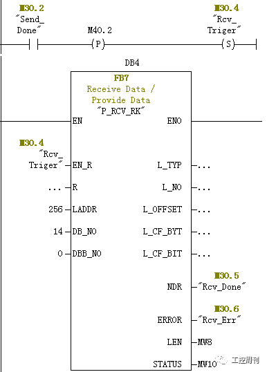
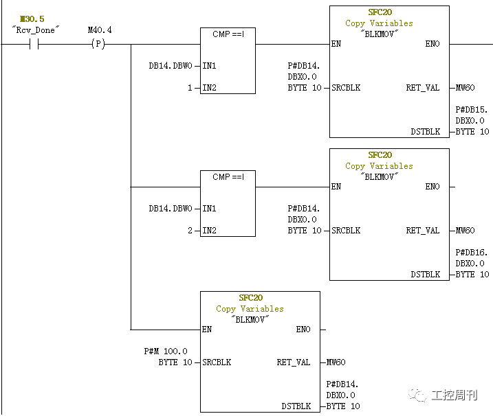
4. Receiving Completed
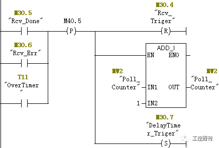
After receiving the data, the following steps are handled: if there is an error or timeout, the current station is skipped. Otherwise, the address data is determined from the received identifier, and the data is transferred to the designated storage area while clearing the receive buffer. The receive flag is reset, the polling counter is updated, and a delay timer is started to prepare for the next station.
8. Slave Program
The slave program is relatively simpler than the master's. For example, the second slave station works similarly to the first, except that different function blocks are called.
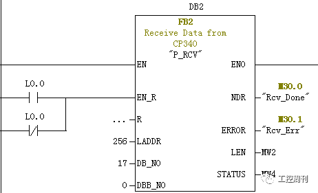
1. Receiving Data
The slave continuously starts the receive function FB2 P_RCV to receive data from the network. If the data is received, it checks whether it is addressed to the current station:
• If it is the correct station, the data is moved to the designated address area (DB18), and the receive buffer (DB17) is cleared. The send flag is triggered, and the return data is sent to the master.
• If it is not the correct station, the receive buffer (DB17) is directly cleared.
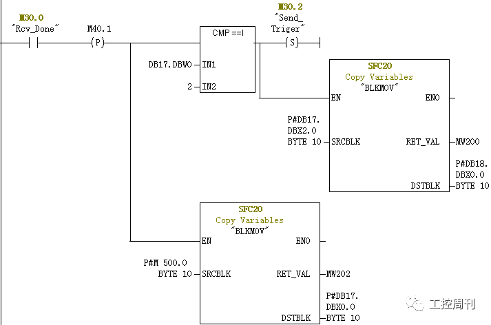
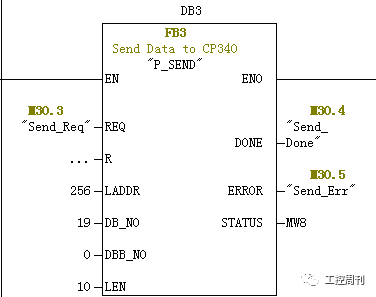
2. Send Return Data
After receiving the data, the send function is called to transmit the data from DB19 back to the master station.
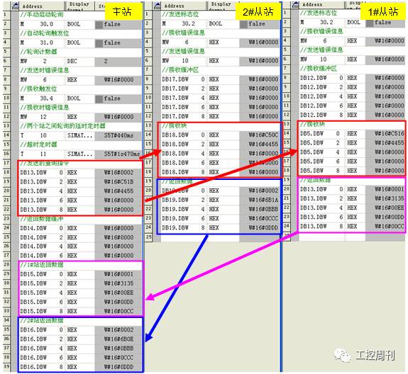
9. Experimental Results
Set up the network, download the program to the respective CPUs, and start the CPUs. The polling program can be initiated by setting the manual start flag M30.0. Using the variable table, you can monitor the system's operation. It shows that the master station cyclically transmits data to both slaves and receives return data from them, as illustrated in the following figure.
Optical Time Domain Reflectometer OTDR
Mini PRO OTDR,OTDR Fiber Optic Tester,handheld otdr,Handheld Smart OTDR Fiber Tester,Optical Light Source
Shenzhen Runtop Technology Co.LTD , https://www.runtoptech.com