In optimizing the design of motion control systems based on stepper motors, engineers must carefully consider a range of factors including cost, performance, efficiency, and unexpected feedback challenges like mechanical resonance. Modern motor control systems often operate in diverse and challenging environments, and traditional solutions tend to be limited by worst-case scenarios across the entire system. To achieve maximum efficiency, adaptive control algorithms are essential for fine-tuning the electromechanical system.
**System Mapping**
To achieve optimal performance, it's crucial to map the boundary conditions of the entire electromechanical system. This involves considering all relevant variables such as temperature, mechanical wear, acceleration, speed, and supply voltage. The system architecture also plays a significant role in determining overall behavior.
In open-loop systems, the motor is often driven with worst-case current and speed profiles, which means efficiency isn’t typically the main design focus. However, this approach requires extensive testing at various supply voltages, temperatures, and speeds to minimize the risk of resonance. Resonance can cause the motor to lose steps or stall, making it a critical issue. Yet, identifying these problematic areas in open-loop systems can be quite challenging.
Closed-loop control systems usually come in two forms: sensor-based (like optical or Hall effect sensors) and sensorless systems. Sensorless systems, sometimes referred to as "semi-closed loop," use the back EMF generated by the motor coils as feedback. While sensor-based systems are common, they require additional components that complicate the design. Sensorless systems offer advantages such as lower cost, reduced complexity, and the ability to monitor physical motor movement directly. A key factor in successful implementation is understanding the characteristics of the back EMF.
**SLA Mapping**
Back EMF provides detailed insights into the motion of the electromechanical system and serves as a diagnostic tool. It generates a voltage between drive current pulses and the movement of the motor coil through the magnetic field. This data is often referred to as the Speed and Load Angle (SLA) of the motor. The angular velocity of a stepper motor can be accurately estimated by monitoring the magnitude of the back EMF.
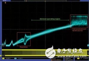
Figure 1 illustrates the mapping of SLA pins while driving a conventional stepper motor using the AMIS-30522 controller. The data was collected during an NXT input sweep, which controls the motor’s excitation speed. As the frequency increases from left to right, distinct operational zones become visible. The AMIS-305xx series offers powerful capabilities for analyzing motor characteristics, helping to address traditional design issues—such as resonance—which were previously only studied in isolation, without considering how the full mechanical system might affect them.
The motor control system can continuously sample the SLA voltage and take corrective actions if anomalies occur. Since back EMF is proportional to the rotor’s rotational speed, it can be used to sense external loads on the output shaft and adjust the motor’s current accordingly. Additionally, SLA data is valuable when the motor is approaching a resonant region. An algorithm can detect this situation quickly and accelerate the motor through the unstable zone to reach a safer speed.
The red square on the left side of Figure 1 highlights a resonant area, which may result from the motor’s installation, its natural frequency, or other secondary factors. These are regions where commutation should be avoided. Using ON Semiconductor’s back EMF technology, these areas can be mapped efficiently within minutes, reducing system stress. This is important because excessive pressure can lead to noise, degraded performance, and reduced reliability. Notably, this method allows for mapping without any physical modifications to the system, relying solely on the motor itself as a sensor, thus avoiding extra mechanical complexity.
On the right side of Figure 1, the red square shows the area where the current drive exceeds the RLC time constant of the system, leading to residual current in the motor coil. This represents the “speed limit†for this particular system.
Between these two zones lies the recommended operating area for the motor. It’s also worth noting that the same mapping process can identify stall conditions where the motor fails to commutate and thus cannot generate back EMF. In such cases, the system controller can manage the situation by setting a minimum threshold between motor excitations.
**Using Mapping Data in Your Design**
Once the mapping is complete and the ideal speed profile is identified, the best SLA value can be selected for a given system, representing the most efficient operating point. Motor control parameters such as current, acceleration, and speed can be dynamically adjusted to avoid inefficiencies caused by resonance or excessive current. The advantage of the sensorless/back EMF method is that it provides rich diagnostic information without adding complexity, allowing real-time adjustments to prevent step loss and improve overall system performance.
Three Phase Vfd,Ac Single Phase Gasoline Generator,220V Vfd,Ac Inverter
WuXi Spread Electrical Co.,LTD , https://www.vfdspread.com