How to see the timing diagram of the microcontroller A/D converter ADC0804

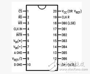
The ADC0804 is a monolithic integrated analog-to-digital converter that utilizes a CMOS process. It is packaged in a 20-pin IC with an 8-bit resolution, a conversion time of 100μs, and an input voltage range from 0 to 5V. The chip features a three-state output data latch, allowing it to be directly connected to a microcontroller's data bus for seamless integration. 
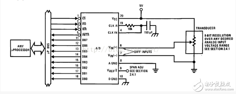
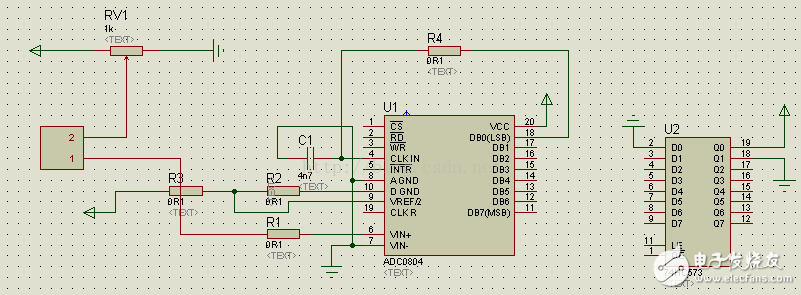
As shown in the figure, the ADC0804 is a single-chip A/D converter designed for easy use in various applications:

How to see the timing diagram of the microcontroller A/D converter ADC0804

Below are the functions of each pin: - **VIN(+), VIN(-)**: These are the analog input terminals that can handle unipolar, bipolar, or differential signals. - **DB7–DB0**: These are the 8-bit digital output lines with three-state functionality, allowing them to interface directly with a microprocessor. - **AGND**: Analog ground reference for the input signals. - **DGND**: Digital ground reference for the internal circuitry. - **CLK**: Clock signal input used to synchronize the conversion process. - **CLKR**: External resistor used with the CLK pin to set the internal clock frequency, which is calculated as 1/(1.1RC). - **CS#**: Chip select signal, active low, which enables the ADC0804 to start operation. - **WR#**: Write signal, active low, which initiates the A/D conversion. - **RD#**: Read signal, active low, which allows the microcontroller to read the converted digital data. - **INTR#**: Interrupt signal, active low, indicating that the conversion has completed. - **VREF/2**: Reference voltage input that defines the quantization step size. - **VCC**: Power supply input, typically 5V. By referring to the ADC0804 datasheet, you can find typical connection diagrams for proper implementation:

How to see the timing diagram of the microcontroller A/D converter ADC0804

You can also simulate the ADC0804’s operation using electronic design software to better understand its timing and behavior:

How to see the timing diagram of the microcontroller A/D converter ADC0804

In summary, the ADC0804 is a versatile and widely used A/D converter that simplifies the integration of analog signals into digital systems. Its straightforward pinout, ease of configuration, and compatibility with microcontrollers make it a popular choice in many embedded applications. Whether you're designing a sensor interface, a control system, or a data acquisition module, the ADC0804 offers reliable performance at an affordable cost.

Flux-cored Solder Wire

This Solder Wire is with activated resin flux,It enjoys excellent weld ability,which can be divided into RA and RMA.which is made from extremely high purity raw materials.

Sn63/Pb37,Sn60/Pb40,Sn50/Pb50,Sn45/Pb55,Sn40/Pb60,Sn30/Pb70

Flux-Cored Solder Wire,Solder Welding Wire,Lead Free Solder Wire,Silver Solder Wire

Shaoxing Tianlong Tin Materials Co.,Ltd. , https://www.tianlongspray.com