The internal structure of the LTC3526/LTC3526B and its external component connections in the application are shown below.
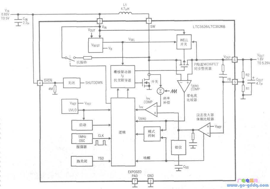
Both ICs feature separate startup oscillators that can be activated at an input voltage as low as 0.85V. The chip provides a soft-start function and limits inrush current during startup and normal operation. Once the input or output voltage exceeds 1.4V, the IC enters normal operating mode. When the output voltage is higher than the input voltage by 0.24V, the IC switches to self-powering from the output, allowing for the use of a smaller input capacitor. Even when VIN drops to 0.5V, the IC continues to operate with the duty cycle clamped at 90%. During the soft-start phase, the inductor current ramps up from 0 to 700mA within 0.5ms. In off mode, the soft-start circuit resets. For 60ns, the peak switch current is limited to 700mA. A zero-current comparator monitors the inductor current and turns off the synchronous rectifier when the current drops to about 30mA, improving efficiency under light loads.
An anti-ringing circuit is connected across the external inductor, helping to suppress high-frequency ringing on the SW pin and reduce EMI radiation. The LTC3526/LTC3526B allow the actual output to be disconnected. During the IC's off period, VOUT can be set to 0V without drawing current from the input, and VOUT can rise freely without reverse current flowing into the battery.
The LTC3526 automatically enters burst mode operation at light loads, switching back to fixed-frequency PWM mode when the load increases. The LTC3526B operates at a frequency of 1MHz and disables pulse skipping under very light loads. Even when VIN is greater than VOUT, the LTC3526/LTC3526B maintain voltage regulation, although with lower efficiency and reduced maximum output current. If the SHDN pin voltage is below 0.3V, the IC turns off; if it’s above 0.8V, the IC is enabled. When the die junction temperature exceeds 160°C, the IC enters shutdown mode and re-enables once the temperature drops below 145°C.
Ll recommends using a 3.3–6.8μH chip inductor with low equivalent series resistance (ESR). The allowable inductor current ripple (peak-to-peak) is typically 30% of the maximum inductor current. The minimum inductor value is calculated using the following formula:
![]()
![]()
In the application circuit of the LTC3526/LTC3526B, the input capacitor CIN can be a low-ESR 1μF ceramic capacitor, while the output capacitor COUT should be a 4.7–10μF low-ESR multilayer ceramic capacitor.
This website focuses on promoting advertising services for small and micro-enterprises. We recommend cost-effective and efficient solutions. Feel free to contact us via QQ or email!
Why do you want to do online advertising?
- 0
- like
| Try to find the information you want to see. Inverter sensor patch three no weight loss camera LCD monitor does not boot digital camera XC9237XC6102 projector switching power supply laptop processor IPSUSB skills entrepreneurial black screen XC6112 water heater can not boot circuit design silent transformer without sound display regulator no image microwave player successful silent GPS Tea no picture XC6222 health XC6372 relay filter ML6209 washing machine switch digital camera description remote control without grating 555 protection circuit cancer self-closing Linux mobile phone charger shutdown noise inverter oscilloscope robot Windows antenna indicator light does not bright fiber life transformer stomach market alarm Hard disk watch embedded system woman maintenance process memory XC9236 converter XC6371 router interview server kidney RFIDLED driver Konka CDMA instrument Panasonic Apple CCD flashing engine multimeter liver motor resistance keyboard integrated circuit current transformer triode governor electric water heater |
Core Components & How It WorksÂ
integrated amps,integrated stereo amplifier,integrated stereo amp,2000 watt amplifier,class a amp
Guangzhou Aiwo Audio Technology Co., LTD , https://www.aiwoaudio.com