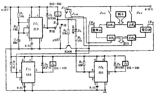
The circuit is shown in the figure, where IC1 is a timed square wave oscillator, IC2 and IC3 are both used as hysteresis comparators, and DF1-DF4 is a normally closed electromagnetic threshold to control the flow of liquid. A and B are two dosing cylinders, and the liquid level is measured by the probes INA and INB, respectively.
Relay J1 controls the liquid electromagnetic thresholds DF1 and DF2, and relays J2 and J3 control the quantitative liquid input electromagnetic thresholds DF3 and DF4, respectively.
A transmitter sends both audio and video signals over the air waves. Transmitters usually transmit more than one signal (TV channel) at a time. A transmitter modulates both picture and sound into one signal and then send this transmission over a wide range to be received by a receiver (TV set).
It is an electronic device that radiates radio waves that carry a video signal representing moving images, along with a synchronized audio channel, which is received by television receivers ('televisions' or 'TVs') belonging to a public audience, which display the image on a screen.
Dtv Transmitter,Vhf Uhf Tv Transmitter,Terrestrial Tv Transmitter,Tv Channel Transmitter
Anshan Yuexing Technology Electronics Co., LTD , https://www.yxhtfmtv.com