The CAN bus design specification has strict regulations on the output voltage of the CAN node. If the output voltage of a single node does not meet the specifications, the signal level is unreliable after field networking, resulting in the occurrence of error frames. Unable to communicate. The specific requirements are shown in Table 1, which is the test standard "ISO 11898-2 output voltage standard".
This article refers to the address: http://
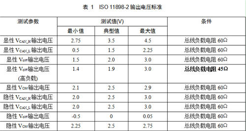
Therefore, each manufacturer must test the output voltage amplitude of the CAN node DUT (device under test) before the product is put into use. Generally, the CAN test method using the ISO 11989-2 output voltage standard is as follows:
As shown in Table 1, under load conditions, select the adaptation conditions of the DUT under test. As shown in Figure 1, Rtest is the network load resistance, which is normally 60Ω and 45Ω at high load. The absolute and differential voltage levels and CANL CANH line voltage of 14 V. In addition, measure the common mode bus voltage VCM. Voltage: VCAN_H, VCAN_L, then calculate the differential voltage Vdiff and the common mode voltage VCM. The calculation methods of Vdiff and VCM are as follows:
Vdiff = VCAN_H – VCAN_L
VCM = 0.5 * (VCAN_H + VCAN_L)
If the test results meet the requirements shown in Table 1, pass the test.
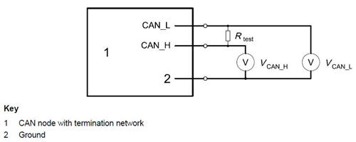
Figure 1 Output voltage test principle
It can be seen that although the method can measure the output voltage of the signal, the test system is cumbersome to build, and it is necessary to take multiple measurements to calculate the average value, and measurement errors may occur, which wastes manpower and material resources.
Therefore, Guangzhou Zhiyuan Electronics Co., Ltd. improved the test method. After using the CANScope-Pro bus analyzer and the CANScope-StressZ expansion board, the symmetry test method was adopted to avoid the error of manual measurement and statistics, and at the same time, the method of automatic test was adopted. The waste of test time is reduced, and the statistical measurement of large data volume is realized, the accuracy of the test is improved, and the labor cost is greatly saved.
The test plan is as follows:
1. After the DUT is powered on, CAN messages can be sent all the time. CANScope does not check the bus response. Its black test pen (ground) should be shared with the CAN transceiver of the DUT. As shown in Figure 2, the analog interference of the Stress board is configured. Parameters for testing connections to the test system.
According to the corresponding test conditions, the analog load resistance is changed by adjusting the RHL value on the CANScope-StressZ analog expansion board (RHL=60Ω for normal test and RHL=45Ω for high load test). Perform DUT output differential drive capability test.
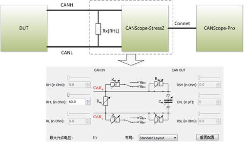
Figure 2 output voltage test connection diagram
2. Start CANScope-StressZ and CANScope, record the message and waveform for a period of time (at least 10,000 frames or more), click CANScope to stop and save. Then click on the “symmetry test†in “Test†to perform the automatic test of the common mode voltage VCM, as shown in Figure 3:

Figure 3 CANScope symmetry test
3. Go to the Symmetry Test setup screen, as shown in Figure 4. Click the "Auto Setup" button to adjust the voltage range and offset, then set the error voltage to 0.25 to meet the VCM requirements for both dominant and recessive levels, then click to start the test.
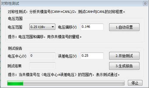
Figure 4 Symmetry test common mode voltage
4. After waiting for the progress bar to complete, click “Generate Report†to get the test results, as shown in Figure 5.
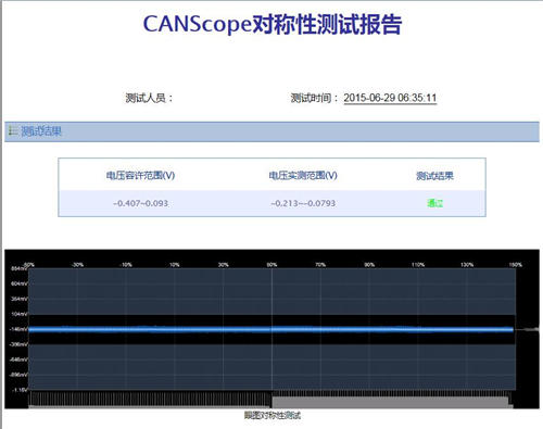
Figure 5 software eye diagram add configuration
5. As shown in Figure 6, click on the “CAN Tester†in “Test†to test the CAN_H, CAN_L, and CAN_DIFF parameters.
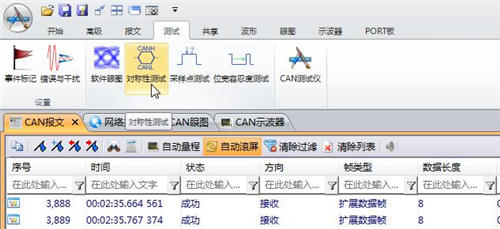
Figure 6 CAN tester automatic test
6. Keep the DUT (tested device) in the transmit data state, as shown in Figure 7, enter the "CAN Tester" interface, check the voltage test, fill the VCAN_H, VCAN_L, Vdiff requirements in ISO11898-2 into the voltage test. , click "Open". After waiting for the test to finish, you can click the “Test Report†button to generate the test report file as shown in Figure 8.
Note: Since the recessive maximum of the CANScope test Vdiff cannot be set to 0.05V, it can only be set to 0.5V, so this test option should be accurately tested with a ZDS2024 oscilloscope with a differential probe.
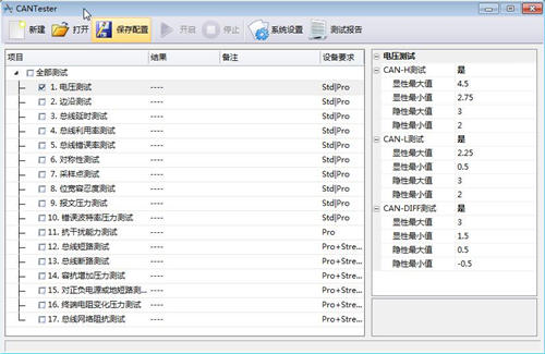
Figure 7 CAN Tester - Voltage Test
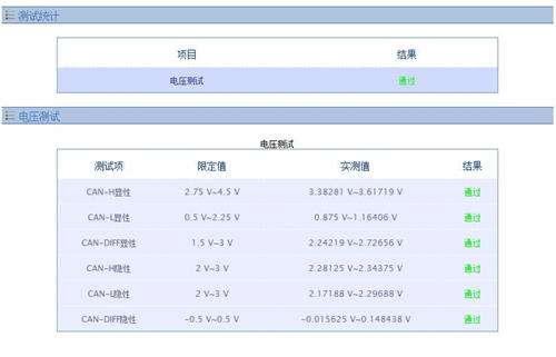
Figure 8 voltage test report
CANScope analyzer is a comprehensive CAN bus development and testing tool developed by Zhou Ligong Zhiyuan Electronics. It integrates mass storage oscilloscope, network analyzer, bit error rate analyzer, protocol analyzer and reliability test tool. Integrate and correlate various instruments organically; redefine the development and test methods of CAN bus, and evaluate the correctness, reliability and rationality of CAN network communication in multiple angles; help users quickly locate faulty nodes and solve CAN bus The various problems of the application are the ultimate tools for CAN bus development testing.
Here you can find the related products in Led Panel Light , we are professional manufacturer of LED Panel Light , Smd Led Panel ,Ultra Thin Panel Light, Led Lighting 36W and Round Panel Light, Dimmable Panel Light, We focused on international export product development, production and sales. We have improved quality control processes of LED Panel Light to ensure each export qualified product.
If you want to know more about the products in LED Panel Light, please click the product details to view parameters, models, pictures, prices and other information about LED Panel Light. Whatever you are a group or individual, we will do our best to provide you with accurate and comprehensive message about LED Panel Light!

LED Panel Light
Led Panel Light,Smd Led Panel,Ultra Thin Panel Light,Led Lighting 36W
Guangdong Decosun Lighting Technology Co.,Ltd , https://www.decosun-lighting.com