Guide: Solid State Relay is an electronic switching device that operates without mechanical parts. This article will explore the working principle of solid state relays, explaining how they function and why they are widely used in modern electronics. Let's dive into the details with Xiaobian.
1. Solid State Relay Working Principle – Introduction
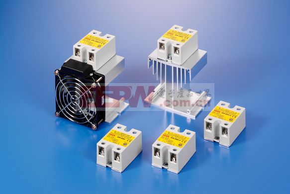
A Solid State Relay (SSR) is a contactless electronic switch that combines microelectronics and power electronics technologies. It has four terminals: two for input and two for output. The isolation mechanism ensures electrical separation between the input and output, making it ideal for applications where safety and noise reduction are essential. SSRs can be categorized based on the type of load power supply (AC or DC), switch type (normally open or normally closed), and isolation method (optocoupler, transformer, or photoelectric). Among these, the optocoupler isolation is the most commonly used due to its reliability and performance.
2. Solid State Relay Working Principle – Structure
SSRs are designed to control high current loads using a low-level signal, allowing for contactless switching. They consist of three main components: the input circuit, the isolation and coupling section, and the output circuit. The input circuit processes the control signal and varies depending on whether it’s AC, DC, or both. The isolation component, often an optocoupler or transformer, ensures that the input and output remain electrically separated. The output circuit includes a power switch, such as a triac or MOSFET, which connects or disconnects the load from the power source.

3. Working Principle of Solid State Relay
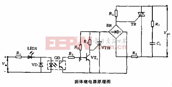
This article focuses on the AC zero-crossing SSR, which is one of the most widely used types. It uses zero-crossing triggering technology, meaning it turns on when the AC voltage passes through zero and turns off when the current drops to zero. This results in minimal electromagnetic interference and a clean sine wave on the load, making it suitable for sensitive applications.
The internal circuit includes a signal input section, a zero-voltage detection circuit, a status indicator, a triac control unit, and a damping circuit. An optocoupler (GD) is used for isolation between the input and output, while a diode (VD) prevents reverse voltage from damaging the optocoupler. When no input signal is present, the phototransistor remains off, keeping the triac in the off state. When a signal is applied, the phototransistor turns on, allowing the triac to trigger only when the voltage crosses zero, ensuring safe and efficient operation.
For further reading:
- 1. The difference between DC solid state relay and AC solid state relay
- 2. Introduction to solid state relays and their working principle
- 3. Essential circuit design tools for engineers
Understanding the working principles of solid state relays helps in choosing the right type for specific applications, ensuring efficiency, safety, and long-term reliability in various electronic systems.
Oblique Single Axis Solar Tracker System
Oblique Single Axis Solar Tracker System,Oblique Single Axis Solar Tracker System Customized,oblique single axis solar tracker system device
Hebei Jinbiao Construction Materials Tech Corp., Ltd. , https://www.pvcarportsystem.com