Guide: Solid State Relay is an electronic switching device that has no moving parts. This article explores the working principle of solid state relays, explaining how they function and why they are widely used in modern electronics. Let’s dive into the details with Xiaobian.
1. Working Principle of Solid State Relay – Introduction
A Solid State Relay (SSR) is a contactless electronic switch developed by combining modern microelectronics and power electronics technologies. It operates as a four-terminal device, where two terminals are for input and the other two for output. The isolation mechanism ensures electrical separation between the input and output sides. SSRs can be categorized into AC and DC types based on the load power supply. They can also be classified by switching type—normally open or normally closed—and by isolation method, such as hybrid, transformer-isolated, or optically isolated. Among these, the opto-isolated type is the most commonly used due to its reliability and safety.
2. Working Principle of Solid State Relay – Structure
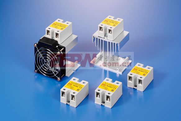
As a new generation of contactless switching devices, SSRs allow control of currents ranging from 0.1A up to hundreds of amperes using weak control signals. The internal structure of an SSR typically includes three main components: the input circuit, the isolation stage, and the output circuit.
Input Circuit: Depending on the input voltage type, it can be designed as DC input, AC input, or a combination of both.
Isolation Coupling: This part uses optocouplers or transformer coupling to isolate the input and output circuits, ensuring electrical safety and reducing interference.
Output Circuit: This section connects directly to the power supply and the load, enabling the switching of the load’s power supply without physical contacts.

3. Working Principle of Solid State Relay
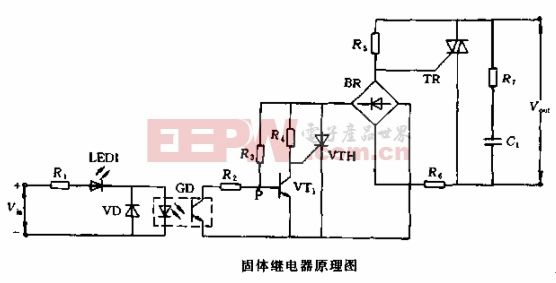
In this section, we’ll focus on the AC zero-crossing SSR, which is one of the most commonly used types. This design uses zero-crossing triggering technology, meaning it turns on when the voltage crosses zero and turns off when the current reaches zero. This approach minimizes electromagnetic interference and ensures a clean sinusoidal waveform on the load.
The circuit consists of several key parts: a signal input circuit, a zero-voltage detection control circuit, a working indicator circuit, a triac control circuit, and an absorption circuit. A phototransistor (GD) is used for isolation between the input and output, while a diode (VD) prevents reverse voltage damage to the GD.
During operation, when no input signal is present, the phototransistor in GD is off, and the base current of VT1 is controlled via resistor R3. This keeps the gate of VTH at a low potential, keeping the relay in the off state. When an input signal is applied, the phototransistor turns on, allowing VT1 to conduct. If the AC voltage exceeds the zero-crossing threshold, the voltage at point P (from resistors R3 and R2) becomes higher than VBE1, causing VT1 to saturate and turn off the SCR gate. However, if the voltage is below the zero-crossing point, the gate of the TR is triggered, turning it on and allowing the load to receive power.
Expand Reading:
- The difference between DC solid state relay and AC solid state relay
- Introduction to solid state relays and their working principle
- Essential circuit design tools every engineer should know
Whether you're a student, engineer, or tech enthusiast, understanding how solid state relays work can help you make better decisions in your projects. With their reliability, efficiency, and long lifespan, SSRs have become an essential component in many electronic systems today.
Flat Single Axis Solar Tracker System
Flat Single Axis Solar Tracker System,Single Axis Solar Tracker System,Single Axis Solar Tracker System customization
Hebei Jinbiao Construction Materials Tech Corp., Ltd. , https://www.pvcarportsystem.com