Abstract: This applicaTIon note discusses the 1-Wire® File Structure (OWFS). The OWFS provides a directory structure for data residing in 1-Wire devices including iButtons. It allows named files to be randomly accessed as they are on other file systems. The "Book of DS19xx iButton Standards" provides a basic specificaTIon of the file structure. This document extends the basic definiTIon to include bitmap files for large capacity 1-Wire devices, mulTIple subdirectories, extended file attributes, and other useful constructs, including files spanning multiple devices.
I. 1-Wire File StructureThe 1-Wire File Structure (OWFS) provides a directory structure for data residing in 1-Wire devices including iButtons. It allows named files to be randomly accessed as they are on other file systems. The "Book of DS19xx iButton Standards "provides a basic specification of the file structure. This document extends the basic definition to include bitmap files for large capacity 1-Wire devices, multiple subdirectories, extended file attributes, and other useful constructs.
The definitions and rules of the OWFS are sufficient to store multiple files in nested directories using device capacities up to 16M bytes. These devices may be organized as 2-65535 pages of 32-256 bytes. The rules given in this document are scaleable to all combinations of memory organization within this range including structures that spans multiple devices. (Note that in all discussions of this data structure, the first available page of memory is called page 0).
A. Data OrganizationThe data organization of the OWFS is divided into sectors that correspond to a page of memory on a 1-Wire device. Each page used in the file structure has its data wrapped in a packet as outlined in Figure 1. A directory tells which files are stored, where the data is located in the device, and how many pages it occupies. In this way information can be randomly accessed for quick response.
The organization of data within a page used by the file structure is shown below.
Figure 1. Data packet.
Each page of a file or directory begins with a length byte, contains data (at least a continuation pointer), and ends with an inverted CRC16 check. The length byte indicates how many valid bytes a page contains, not counting the length byte itself or the CRC. The CRC calculation, however, also includes the length byte. The CRC accumulator is initialized by setting it equal to the 1-Wire device absolute page number. Every byte of a page is transmitted to or from a 1-Wire device least significant bit first. The length byte is the first to be transmitted. Of the 2 CRC bytes, the least significant will be sent first. Since all of the pages used in this file structure use this format (only the 'data' portions of the packet will be displayed in the other Figures in this section) the length and CRC will be assumed.
A common component in the 'data' portion of all packets used in this file structure is the 'continuation pointer'. The continuation pointer is the page address where the file or directory is continued. Like other values ​​that represent a page number, the continuation pointer can be represented with one or two bytes depending on the number of pages in the file system. For this reason, the figures in this section will display page numbers as being 'N' bytes long. The following discussion of the contents of the root directory's 'control data' describes when page numbers are one or two bytes. A continuation pointer value of 0 marks the last page in the file or directory. Figure 2 displays the typical 'data' payload of a page participating in the file structure.
Figure 2. Continuation pointer.
Each memory 1-Wire device must be formatted before it can be used with the OWFS. During the process of formatting, the root directory file is created. The root directory always begins in the first page of the device (page 0). The organization of data within the first page of the root directory is shown in Figure 3.
Figure 3. Root directory start.
Instead of data, the directory contains management information and file entries. The control field begins with a directory marker byte (DM) that specifies the type of OWFS. The most significant nibble (DM7-DM4) is a hex 'A' if the entire file structure is contained on only one 1-Wire device and a hex 'B' if it is spans multiple devices. The least significant nibble (DM3-DM0) designates whether the continuation pointers, start page, and number of page values ​​are one or two bytes long. A hex 'A' in this position indicates one byte is used and a hex 'B' indicates two bytes are used. The two-byte number is an unsigned integer with the least significant byte first. With these two options, there are a total of four types of file structure flavors as seen in Figure 4. Note that the previous version of this specification covered only the 'AA' type of file structure (one device with no more then 256 pages).
Figure 4. File structure types.
When the file structure spans multiple devices (DM7-DM4 is hex 'B'), then the map address (MA) in the control data field specifies a starting page for a device map file that contains a list of the 1-Wire devices participating in this file structure. If the file structure does not span multiple devices (DM7-DM4 is hex 'A') then the map address (MA) is zero. Note that EPROM-based devices cannot be used in a multiple device file structure.
If the directory mark (DM) indicates that this file system spans multiple devices, then the second to least significant bit (BC1) in the bitmap control byte indicates if this device is the 'MASTER' device (1) or a 'SATELLITE' device (0). If the device is the 'MASTER' device, then the map address (MA) specifies a page number for a file that contains an ordered list of the 'SATELLITE' devices. If the device is a 'SATELLITE' device, then it contains a single device indicating the 'MASTER' device. Each device specified in a map file is an eight-byte binary 1-Wire net address least significant byte first. To save on space and prevent a 1-Wire master from altering it , a 'SATELLITE' device will always have a local bitmap (see BC7 description below) with all of the pages marked as used. To be valid, the map file and if necessary, the bitmap file, must fit on the 'MASTER' device . Multi-device file structures can consist of devices with different memory sizes. The number of pages is known by ref erencing the family code of each device. If the 'MASTER' device has X pages then page X + 1 is the first page of the first 'SATELLITE' device.
The most significant bit of the bitmap control byte (BC7) specifies whether the bitmap is stored immediately in the first directory packet or in a separate file. If this bit is a 1, the 4-byte local bitmap (LBM) immediately follows the bitmap control byte. If the most significant bit (BC7) of the bitmap control byte is 0, then the proceeding 4 bytes specify the starting page address and the number of pages required by the bitmap file. The number of bytes required for each of these values depends on DM. If the page addresses are represented by a 1-byte value (DM3-DM0 = hex 'A') then the first two bytes are 0 followed by a one byte starting page address and a one byte number of pages. If the page addresses are 2-byte values ​​(DM3-DM0 = hex 'B') then the first two bytes contain the starting page address and the next two bytes contain the number of pages. Note that the bitmap or the nameless bitmap and optional device map file are created during the process of formatting. Continuation p ages of the directory don't need a control field. This space is available to store another file entry.
The bitmap of used pages serves as a fast lookup table to find free pages. In this bitmap, used pages are marked with a 1, empty pages with a 0. The least significant bit corresponds to page 0. This local bitmap is only used for non-EPROM devices with less then 32 pages of data. All other devices have remote bitmap files. In large NV-RAM 1-Wire devices, the bitmap file page number refers to normal data space. In EPROM devices, the page number refers to status memory. For EPROM devices, the unprogrammed state is 1 and the programmed state is 0. Due to this constraint, the bits in the EPROM bitmaps are inverted. An empty page has a 1 and an occupied page has a 0.
The least significant bit (BC0) in the bitmap control byte is an in-progress bit. This bit can be set when doing non-interruptible operations like file optimization. The bit is cleared after the operations are complete.
The bits BC2-BC6 of the bitmap control byte are not used and should be zero.
See Section II for examples of each type of file structure.
File entries consist of the 4-byte file name, 1-byte file extension, the starting page address where the file begins, and the number of pages the file occupies. This structure is shown below: (Note that the number of bytes to represent both the starting page and the number of pages depends on the file structure type).
Figure 5. File structure types.
The file entry structure as seen in Figure 5 must remain contiguous and not be split up across directory pages. For example, if a device type has 128 byte pages and the file entry structure is 7 bytes long then 17 whole directory entries can fit per directory page. In this scenario there are 5 extra bytes in each directory page that are not used.
File names must consist of ASCII characters only defined by the following set:
ABCDEFGHIJKLMNOPQRSTUVWXYZ0123456789! # $% & '-@ ^ _ `{} ~
However, if the first byte of a file entry has a value greater than 127, then it represents the first byte of an extended directory entry. The extended directory entry applies to the next directory entry and is the same size as other directory entries depending on the file system type (7 to 9 bytes). There may be multiple extended directory entries but the first byte must greater than 127. The additional bytes in an extended directory entry may be used to specify additional file attributes, passwords, file ownership, date / time stamps, and other special-purpose information regarding the file. The use of extended directory entries is application specific so general implementations of this file structure will ignore them.
The 7 least significant "e" bits of the extension represent the extension number of the file entry. See Figure 6 for a list of file extension types. The most significant bit of the file extension "a" is an attribute flag for the entry. If it is set and the entry is a normal, then the file is read-only. If it is set and the entry is a sub-directory with extension 127 (decimal) then the subdirectory is hidden. File entries denoting subdirectories contain the real "start page" of the subdirectory file. The "# pages" specifier for a subdirectory entry does not contain a valid number. It always contains 0 and need not be updated when the length of a subdirectory file changes. A subdirectory file contains a back reference to the next higher directory file. If there is no higher subdirectory file the entry will be "ROOT." The start page of ROOT is always 0. The first packet of a subdirectory file is seen in Figure 7.
Figure 6. Sub-directory start.
A continuation packet of a root directory or a subdirectory file follows the definition of a data packet. It has the following structure:
Figure 7. Sub-directory continuation.
See Table 1 for list of the available file types.
Table 1. File Types
B. FeaturesThe OWFS is carefully designed to provide high speed and the best performance in a Touch environment. Every memory page can be read, CRC-checked, or written without the need to access other pages. If a file is modified, only the affected Pages need to be rewritten. This provides a significant speed advantage. Pages of a file need not be contiguous. Files can be extended by redefining continuation pointers. Files can be grouped into nested subdirectories. Attributes defined for a directory apply for all files within it .
C. PropertiesThe notes below summarize many of the significant properties of the OWFS as specified above. These notes may be helpful in understanding the implications of the OWFS with regard to data storage and management.
The page length is derived from the family code. 1-Wire devices currently available have a 32-byte page length, but the definition of the OWFS also supports greater page lengths. The number of pages in a device is derived from the family code. Devices with 256 or less pages will have page numbers and number of pages throughout the directory structure represented with one byte. Devices with more than 256 pages will have page numbers and number of pages represented with two bytes, least significant byte first. This will be designated with the DM in the root directory control block. Each page of data in the OWFS is a Universal Data Packet (UDP), starting at a page boundary and never longer than one page. Each UDP starts with a length byte, contains a continuation pointer and ends with a CRC16 check. The pointer indicates the number of the page where a file is continued. A continuation pointer 0 marks the last packet of a file. The length byte indicates the number of bytes between length b yte and CRC. The CRC calculation includes all of the preceding data, including the length byte. The CRC accumulator is initialized by setting it equal to the device page number. Each UDP may be read and CRC-checked independently, without reference to data from other packets. All types of files consist of one or several UDPs. The UDPs contain either application data (data packet) or directory information (directory packet). Every byte of a data packet is transmitted least significant bit first. The length byte is the first to be transmitted. The maximum number of application data bytes within a data packet is page length-continuation, pointer length-3. There is exactly one main directory file in an OWFS. This file is called the root directory and always starts at page 0. The maximum number of entries in the first packet of a sub-directory file is (page length-10 (length byte, control field, CRC)-(continuation pointer length 1 or 2)) / (file entry length 7 or 9 ). The maximum numb er of entries in continuation packets is (page length-3 (length byte, CRC)-continuation pointer length 1 or 2) / (file entry length 7 or 9). The bitmap serves as a fast lookup table to find free pages. The data of the bitmap is treated as a 4-byte binary number. The least significant bit corresponds to page 0. A used page is marked with a 1, an empty page with a 0. The least significant byte of the bitmap is stored at the lower address and is transmitted first. The bitmap file must be used on file structures with a capacity greater than 32 pages. It may be used with smaller devices depending on formatting. Write-once devices always have bitmap files that reside in a special memory area . The polarity of the bits used in the bitmap are reverse from rewritable devices. Special file extensions are 100, 101, and 102. 103 to 126 are reserved and yet to be assigned. Extension 127 is for sub-directories leaving the extensions 0- 99 available for general-purpose application files. There ma y be empty or partially filled data packets. An empty packet consists of the length byte, continuation pointer and CRC16 bytes and acts as pointer to the next data packet of the same file or sub-directory. The unused space must follow the CRC. There is no restriction on the use of empty and partly filled data packets. A file structure is multi-device if the DM is 'BA' or 'BB'. One MASTER and one or more SATELLITE devices can participate in a multi-device file structure . The MASTER has a list of SATELLITE 1-Wire net addresses and each SATELLITE has a dummy directory with a reference back to the MASTER 1-Wire net address. Each SATELLITE device has a local bitmap with all pages marked as used to prevent inadvertent changing . Write-once devices cannot participate in a multi-device file structure. II. File Structure ExamplesThe following section details actual examples of the different types of the OWFS. See Figure 8 and Table 2 for a description of the terminology used in the examples. Pag es not shown are empty of useful data.
Figure 8. Format of file structure examples.
Table 2. File Structure Example Key
File Structure Type 'AA' With Local BitmapDevice: (1) DS1992, Pages: 4 (32-bytes each), Files: one 4-byte file called DEMO. 12.
Page 0, Root Directory
Page 1, Data page of file Demo.12
File Structure Type 'AA' With Bitmap FileDevice: (1) DS1996, Pages: 256 (32-bytes each), Files: one 4-byte file called DEMO. 12.
Page 0, Root Directory
Page 1, Bitmap file of used pages, first page continued on page 2
Page 2, Bitmap file of used pages, last page
(remainder of page not shown)
Page 3, Data page of file Demo.12
(remainder of page not shown)
File Structure Type 'AA' With EPROM Bitmap FileDevice: (1) DS1985, Pages: 64 (32-byte) regular EPROM pages and 10 (8-byte) status EPROM pages, Files: one 4-byte file called DEMO. 12.
Page 0, Root Directory
Page 1, Data page of file Demo.12
(remainder of page not shown)
Page 8 (Status Memory), Bitmap file of used pages, last page
File Structure Type 'AB'Device: (1) DS1998 [future product], Pages: 1024 (128-bytes each), Files: one 4-byte file called DEMO.12.
Page 0, Root Directory
(remainder of page not shown)
Page 1, Bitmap file of used pages, first page continued on page 2
Page 2, Bitmap file of used pages, last page
(remainder of page not shown)
Page 3, Data page of file Demo.12
(remainder of page not shown)
File Structure Type 'BA'Device: (2) DS1993, Pages: 32 (16 pages per device, 32-bytes each), Files: one 4-byte file called DEMO. 12.
Page 0, MASTER Device 06123C23000000E6 (LSByte first), Root Directory
Page 1, Device map containing the SATELLITE 1-Wire net address
(remainder of page not shown)
Page 2, Data page of file Demo.12
(remainder of page not shown)
Page 0, SATELLITE Device 06A16B190000002F (LSByte first), Dummy Root Directory
(remainder of page not shown)
Page 1, Device map containing the MASTER 1-Wire net address
(remainder of page not shown)
File Structure Type 'BB'Device: (2) DS1996, Pages: 512 (256 pages per device, 32-bytes each), Files: one 4-byte file called DEMO.12 placed on SATELLITE device.
Page 0, MASTER Device 0C16B80100000012 (LSByte first), Root Directory
(remainder of page not shown)
Page 1, Bitmap file of used pages, first page continued on page 2
Page 2, Bitmap file of used pages, second page continued on page 3
Page 3, Bitmap file of used pages, last page
(remainder of page not shown)
Page 4, Device map containing the SATELLITE 1-Wire net address
(remainder of page not shown)
Page 0, SATELLITE Device 0C86BA0100000020 (LSByte first), Dummy Root Directory
(remainder of page not shown)
Page 1, Device map containing the MASTER 1-Wire net address
(remainder of page not shown)
Page 2, Data page of file Demo.12
(remainder of page not shown) III. Universal Data Packet The Universal Data Packet (UDP) is a legacy structure used to store data on 1-Wire devices including iButtons. It contains one to two length bytes, data and two inverted CRC16 bytes. The structure is:
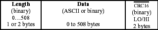
Figure 9. Universal data packet.
The UDPs always start on page boundaries but can end anywhere. The length is the number of data bytes not including the length byte (s) and the CRC16 bytes. There is 1 length byte if the number of data bytes is less then 255. If there are 255 or more data bytes then the first length byte is 255 and the next length byte is 0 to 253. The first and second length bytes added together provide the number of data bytes. The CRC16 is first initialized to the starting page number. This provides a check to verify the page that was intended to be being read. The CRC16 is then calculated using the length and data bytes. The CRC16 is then inverted and stored low byte first followed by the high byte. A detailed description of the CRC16 can be found in Application Note 27.
The OWFS uses a subset of the UDP. It limits the length so that the whole structure will fit in one page. For devices with 32 bytes per page, the length is limited to 29 data bytes. The last data byte is used as a continuation pointer leaving 28 true data bytes. The Default Data Structure (DDS) is a previous standard that specifies only one UDP starting at page 0. This standard does not provide a directory or file type operations but it has speed advantages for simple applications.
I. 1-Wire File StructureThe 1-Wire File Structure (OWFS) provides a directory structure for data residing in 1-Wire devices including iButtons. It allows named files to be randomly accessed as they are on other file systems. The "Book of DS19xx iButton Standards "provides a basic specification of the file structure. This document extends the basic definition to include bitmap files for large capacity 1-Wire devices, multiple subdirectories, extended file attributes, and other useful constructs.
The definitions and rules of the OWFS are sufficient to store multiple files in nested directories using device capacities up to 16M bytes. These devices may be organized as 2-65535 pages of 32-256 bytes. The rules given in this document are scaleable to all combinations of memory organization within this range including structures that spans multiple devices. (Note that in all discussions of this data structure, the first available page of memory is called page 0).
A. Data OrganizationThe data organization of the OWFS is divided into sectors that correspond to a page of memory on a 1-Wire device. Each page used in the file structure has its data wrapped in a packet as outlined in Figure 1. A directory tells which files are stored, where the data is located in the device, and how many pages it occupies. In this way information can be randomly accessed for quick response.
The organization of data within a page used by the file structure is shown below.
Figure 1. Data packet.
Each page of a file or directory begins with a length byte, contains data (at least a continuation pointer), and ends with an inverted CRC16 check. The length byte indicates how many valid bytes a page contains, not counting the length byte itself or the CRC. The CRC calculation, however, also includes the length byte. The CRC accumulator is initialized by setting it equal to the 1-Wire device absolute page number. Every byte of a page is transmitted to or from a 1-Wire device least significant bit first. The length byte is the first to be transmitted. Of the 2 CRC bytes, the least significant will be sent first. Since all of the pages used in this file structure use this format (only the 'data' portions of the packet will be displayed in the other Figures in this section) the length and CRC will be assumed.
A common component in the 'data' portion of all packets used in this file structure is the 'continuation pointer'. The continuation pointer is the page address where the file or directory is continued. Like other values ​​that represent a page number, the continuation pointer can be represented with one or two bytes depending on the number of pages in the file system. For this reason, the figures in this section will display page numbers as being 'N' bytes long. The following discussion of the contents of the root directory's 'control data' describes when page numbers are one or two bytes. A continuation pointer value of 0 marks the last page in the file or directory. Figure 2 displays the typical 'data' payload of a page participating in the file structure.
Figure 2. Continuation pointer.
Each memory 1-Wire device must be formatted before it can be used with the OWFS. During the process of formatting, the root directory file is created. The root directory always begins in the first page of the device (page 0). The organization of data within the first page of the root directory is shown in Figure 3.
Figure 3. Root directory start.
Instead of data, the directory contains management information and file entries. The control field begins with a directory marker byte (DM) that specifies the type of OWFS. The most significant nibble (DM7-DM4) is a hex 'A' if the entire file structure is contained on only one 1-Wire device and a hex 'B' if it is spans multiple devices. The least significant nibble (DM3-DM0) designates whether the continuation pointers, start page, and number of page values ​​are one or two bytes long. A hex 'A' in this position indicates one byte is used and a hex 'B' indicates two bytes are used. The two-byte number is an unsigned integer with the least significant byte first. With these two options, there are a total of four types of file structure flavors as seen in Figure 4. Note that the previous version of this specification covered only the 'AA' type of file structure (one device with no more then 256 pages).
Figure 4. File structure types.
When the file structure spans multiple devices (DM7-DM4 is hex 'B'), then the map address (MA) in the control data field specifies a starting page for a device map file that contains a list of the 1-Wire devices participating in this file structure. If the file structure does not span multiple devices (DM7-DM4 is hex 'A') then the map address (MA) is zero. Note that EPROM-based devices cannot be used in a multiple device file structure.
If the directory mark (DM) indicates that this file system spans multiple devices, then the second to least significant bit (BC1) in the bitmap control byte indicates if this device is the 'MASTER' device (1) or a 'SATELLITE' device (0). If the device is the 'MASTER' device, then the map address (MA) specifies a page number for a file that contains an ordered list of the 'SATELLITE' devices. If the device is a 'SATELLITE' device, then it contains a single device indicating the 'MASTER' device. Each device specified in a map file is an eight-byte binary 1-Wire net address least significant byte first. To save on space and prevent a 1-Wire master from altering it , a 'SATELLITE' device will always have a local bitmap (see BC7 description below) with all of the pages marked as used. To be valid, the map file and if necessary, the bitmap file, must fit on the 'MASTER' device . Multi-device file structures can consist of devices with different memory sizes. The number of pages is known by ref erencing the family code of each device. If the 'MASTER' device has X pages then page X + 1 is the first page of the first 'SATELLITE' device.
The most significant bit of the bitmap control byte (BC7) specifies whether the bitmap is stored immediately in the first directory packet or in a separate file. If this bit is a 1, the 4-byte local bitmap (LBM) immediately follows the bitmap control byte. If the most significant bit (BC7) of the bitmap control byte is 0, then the proceeding 4 bytes specify the starting page address and the number of pages required by the bitmap file. The number of bytes required for each of these values depends on DM. If the page addresses are represented by a 1-byte value (DM3-DM0 = hex 'A') then the first two bytes are 0 followed by a one byte starting page address and a one byte number of pages. If the page addresses are 2-byte values ​​(DM3-DM0 = hex 'B') then the first two bytes contain the starting page address and the next two bytes contain the number of pages. Note that the bitmap or the nameless bitmap and optional device map file are created during the process of formatting. Continuation p ages of the directory don't need a control field. This space is available to store another file entry.
The bitmap of used pages serves as a fast lookup table to find free pages. In this bitmap, used pages are marked with a 1, empty pages with a 0. The least significant bit corresponds to page 0. This local bitmap is only used for non-EPROM devices with less then 32 pages of data. All other devices have remote bitmap files. In large NV-RAM 1-Wire devices, the bitmap file page number refers to normal data space. In EPROM devices, the page number refers to status memory. For EPROM devices, the unprogrammed state is 1 and the programmed state is 0. Due to this constraint, the bits in the EPROM bitmaps are inverted. An empty page has a 1 and an occupied page has a 0.
The least significant bit (BC0) in the bitmap control byte is an in-progress bit. This bit can be set when doing non-interruptible operations like file optimization. The bit is cleared after the operations are complete.
The bits BC2-BC6 of the bitmap control byte are not used and should be zero.
See Section II for examples of each type of file structure.
File entries consist of the 4-byte file name, 1-byte file extension, the starting page address where the file begins, and the number of pages the file occupies. This structure is shown below: (Note that the number of bytes to represent both the starting page and the number of pages depends on the file structure type).
Figure 5. File structure types.
The file entry structure as seen in Figure 5 must remain contiguous and not be split up across directory pages. For example, if a device type has 128 byte pages and the file entry structure is 7 bytes long then 17 whole directory entries can fit per directory page. In this scenario there are 5 extra bytes in each directory page that are not used.
File names must consist of ASCII characters only defined by the following set:
ABCDEFGHIJKLMNOPQRSTUVWXYZ0123456789! # $% & '-@ ^ _ `{} ~
However, if the first byte of a file entry has a value greater than 127, then it represents the first byte of an extended directory entry. The extended directory entry applies to the next directory entry and is the same size as other directory entries depending on the file system type (7 to 9 bytes). There may be multiple extended directory entries but the first byte must greater than 127. The additional bytes in an extended directory entry may be used to specify additional file attributes, passwords, file ownership, date / time stamps, and other special-purpose information regarding the file. The use of extended directory entries is application specific so general implementations of this file structure will ignore them.
The 7 least significant "e" bits of the extension represent the extension number of the file entry. See Figure 6 for a list of file extension types. The most significant bit of the file extension "a" is an attribute flag for the entry. If it is set and the entry is a normal, then the file is read-only. If it is set and the entry is a sub-directory with extension 127 (decimal) then the subdirectory is hidden. File entries denoting subdirectories contain the real "start page" of the subdirectory file. The "# pages" specifier for a subdirectory entry does not contain a valid number. It always contains 0 and need not be updated when the length of a subdirectory file changes. A subdirectory file contains a back reference to the next higher directory file. If there is no higher subdirectory file the entry will be "ROOT." The start page of ROOT is always 0. The first packet of a subdirectory file is seen in Figure 7.
Figure 6. Sub-directory start.
A continuation packet of a root directory or a subdirectory file follows the definition of a data packet. It has the following structure:
Figure 7. Sub-directory continuation.
See Table 1 for list of the available file types.
Table 1. File Types
| Extension (decimal) | Type | Description |
| 0-99 | Normal | Application specific, no special features |
| 100 | Add | Used on devices that have a self-generated CRC value when reading a page. This permits files that leave the 'Length' and 'CRC' unprogrammed until the page is full. This is much more efficient on one-time-programmable device types. End of file is the last non- (FF hex) byte in the last page of the file (denoted by an unprogrammed (FF hex) continuation pointer. |
| 101 | Money-Counter | File is only one page in length and must reside on a page that has a read-only non rolling-over page-write cycle counter. This counter is used to validate the contents of the money file. |
| 102 | Money-SHA | The file must start and end on the same SHA secret pair. The first page in file must reside on a page with a write cycle counter. See application note on SHA iButtons for details on this file's contents. |
| 103-126 | Reserved | Reserved for future specialty files |
| 127 | Sub-directory |
B. FeaturesThe OWFS is carefully designed to provide high speed and the best performance in a Touch environment. Every memory page can be read, CRC-checked, or written without the need to access other pages. If a file is modified, only the affected Pages need to be rewritten. This provides a significant speed advantage. Pages of a file need not be contiguous. Files can be extended by redefining continuation pointers. Files can be grouped into nested subdirectories. Attributes defined for a directory apply for all files within it .
C. PropertiesThe notes below summarize many of the significant properties of the OWFS as specified above. These notes may be helpful in understanding the implications of the OWFS with regard to data storage and management.
The page length is derived from the family code. 1-Wire devices currently available have a 32-byte page length, but the definition of the OWFS also supports greater page lengths. The number of pages in a device is derived from the family code. Devices with 256 or less pages will have page numbers and number of pages throughout the directory structure represented with one byte. Devices with more than 256 pages will have page numbers and number of pages represented with two bytes, least significant byte first. This will be designated with the DM in the root directory control block. Each page of data in the OWFS is a Universal Data Packet (UDP), starting at a page boundary and never longer than one page. Each UDP starts with a length byte, contains a continuation pointer and ends with a CRC16 check. The pointer indicates the number of the page where a file is continued. A continuation pointer 0 marks the last packet of a file. The length byte indicates the number of bytes between length b yte and CRC. The CRC calculation includes all of the preceding data, including the length byte. The CRC accumulator is initialized by setting it equal to the device page number. Each UDP may be read and CRC-checked independently, without reference to data from other packets. All types of files consist of one or several UDPs. The UDPs contain either application data (data packet) or directory information (directory packet). Every byte of a data packet is transmitted least significant bit first. The length byte is the first to be transmitted. The maximum number of application data bytes within a data packet is page length-continuation, pointer length-3. There is exactly one main directory file in an OWFS. This file is called the root directory and always starts at page 0. The maximum number of entries in the first packet of a sub-directory file is (page length-10 (length byte, control field, CRC)-(continuation pointer length 1 or 2)) / (file entry length 7 or 9 ). The maximum numb er of entries in continuation packets is (page length-3 (length byte, CRC)-continuation pointer length 1 or 2) / (file entry length 7 or 9). The bitmap serves as a fast lookup table to find free pages. The data of the bitmap is treated as a 4-byte binary number. The least significant bit corresponds to page 0. A used page is marked with a 1, an empty page with a 0. The least significant byte of the bitmap is stored at the lower address and is transmitted first. The bitmap file must be used on file structures with a capacity greater than 32 pages. It may be used with smaller devices depending on formatting. Write-once devices always have bitmap files that reside in a special memory area . The polarity of the bits used in the bitmap are reverse from rewritable devices. Special file extensions are 100, 101, and 102. 103 to 126 are reserved and yet to be assigned. Extension 127 is for sub-directories leaving the extensions 0- 99 available for general-purpose application files. There ma y be empty or partially filled data packets. An empty packet consists of the length byte, continuation pointer and CRC16 bytes and acts as pointer to the next data packet of the same file or sub-directory. The unused space must follow the CRC. There is no restriction on the use of empty and partly filled data packets. A file structure is multi-device if the DM is 'BA' or 'BB'. One MASTER and one or more SATELLITE devices can participate in a multi-device file structure . The MASTER has a list of SATELLITE 1-Wire net addresses and each SATELLITE has a dummy directory with a reference back to the MASTER 1-Wire net address. Each SATELLITE device has a local bitmap with all pages marked as used to prevent inadvertent changing . Write-once devices cannot participate in a multi-device file structure. II. File Structure ExamplesThe following section details actual examples of the different types of the OWFS. See Figure 8 and Table 2 for a description of the terminology used in the examples. Pag es not shown are empty of useful data.
Figure 8. Format of file structure examples.
Table 2. File Structure Example Key
| Type | Description |
| L | Length byte |
| CRC | CRC16 byte, always two bytes, bit inverted, LSByte first |
| CP | Continuation Pointer, '0' indicates last page in file or directory |
| E | Empty Space |
| BM | Bitmap byte in remote bitmap file |
| D | Data Byte |
| DM | Directory Mark |
| MA | Map Address for device map in multi-device file structure |
| MD | Device map data |
| LBM | Local Bitmap or bitmap file address and number of pages |
| FN | Filename |
| FX | File extension |
| SP | Start page number of file |
| NP | Number of pages in file |
File Structure Type 'AA' With Local BitmapDevice: (1) DS1992, Pages: 4 (32-bytes each), Files: one 4-byte file called DEMO. 12.
Page 0, Root Directory
| 00 | 01 | 02 | 03 | 04 | 05 | 06 | 07 | 08 | 09 | 0A | 0B | 0C | 0D | 0E | 0F | 10 | 11 | 12 | 13 | 14 | 15 | 16 | 17 | 18 | 19 | 1A | 1B | 1C | 1D | 1E | 1F |
| L | DM | MA | BC | LBM | LBM | LBM | LBM | FN | FN | FN | FN | FX | SP | NP | CP | CRC | CRC | E | E | E | E | E | E | E | E | E | E | E | E | E | E |
| 0F | AA | 00 | 80 | 03 | 00 | 00 | 00 | D 44 | E 45 | M 4D | O 4F | 0C | 01 | 01 | 00 | 73 | A5 |
Page 1, Data page of file Demo.12
| 00 | 01 | 02 | 03 | 04 | 05 | 06 | 07 | 08 | 09 | 0A | 0B | 0C | 0D | 0E | 0F |
| L | D | D | D | D | CP | CRC | CRC | E | E | E | E | E | E | E | E |
| 05 | T 54 | E 65 | S 7E | T 74 | 00 | 07 | 0A |
File Structure Type 'AA' With Bitmap FileDevice: (1) DS1996, Pages: 256 (32-bytes each), Files: one 4-byte file called DEMO. 12.
Page 0, Root Directory
| 00 | 01 | 02 | 03 | 04 | 05 | 06 | 07 | 08 | 09 | 0A | 0B | 0C | 0D | 0E | 0F | 10 | 11 | 12 | 13 | 14 | 15 | 16 | 17 | 18 | 19 | 1A | 1B | 1C | 1D | 1E | 1F |
| L | DM | MA | BC | LBM | LBM | LBM | LBM | FN | FN | FN | FN | FX | SP | NP | CP | CRC | CRC | E | E | E | E | E | E | E | E | E | E | E | E | E | E |
| 0F | AA | 00 | 00 | 00 | 00 | 01 | 02 | D 44 | E 45 | M 4D | O 4F | 0C | 03 | 01 | 00 | 61 | 05 |
Page 1, Bitmap file of used pages, first page continued on page 2
| 00 | 01 | 02 | 03 | 04 | 05 | 06 | 07 | 08 | 09 | 0A | 0B | 0C | 0D | 0E | 0F | 10 | 11 | 12 | 13 | 14 | 15 | 16 | 17 | 18 | 19 | 1A | 1B | 1C | 1D | 1E | 1F |
| L | BM | BM | BM | BM | BM | BM | BM | BM | BM | BM | BM | BM | BM | BM | BM | BM | BM | BM | BM | BM | BM | BM | BM | BM | BM | BM | BM | BM | CP | CRC | CRC |
| 1D | 0F | 00 | 00 | 00 | 00 | 00 | 00 | 00 | 00 | 00 | 00 | 00 | 00 | 00 | 00 | 00 | 00 | 00 | 00 | 00 | 00 | 00 | 00 | 00 | 00 | 00 | 00 | 00 | 02 | 2B | 35 |
Page 2, Bitmap file of used pages, last page
| 00 | 01 | 02 | 03 | 04 | 05 | 06 | 07 | 08 | 09 | 0A | 0B | 0C | 0D | 0E | 0F |
| L | BM | BM | BM | BM | CP | CRC | CRC | E | E | E | E | E | E | E | E |
| 05 | 00 | 00 | 00 | 00 | 00 | FE | 48 |
(remainder of page not shown)
Page 3, Data page of file Demo.12
| 00 | 01 | 02 | 03 | 04 | 05 | 06 | 07 | 08 | 09 | 0A | 0B | 0C | 0D | 0E | 0F |
| L | D | D | D | D | CP | CRC | CRC | E | E | E | E | E | E | E | E |
| 05 | T 54 | e 65 | s 7E | T 74 | 00 | 62 | 42 |
(remainder of page not shown)
File Structure Type 'AA' With EPROM Bitmap FileDevice: (1) DS1985, Pages: 64 (32-byte) regular EPROM pages and 10 (8-byte) status EPROM pages, Files: one 4-byte file called DEMO. 12.
Page 0, Root Directory
| 00 | 01 | 02 | 03 | 04 | 05 | 06 | 07 | 08 | 09 | 0A | 0B | 0C | 0D | 0E | 0F | 10 | 11 | 12 | 13 | 14 | 15 | 16 | 17 | 18 | 19 | 1A | 1B | 1C | 1D | 1E | 1F |
| L | DM | MA | BC | LBM | LBM | LBM | LBM | FN | FN | FN | FN | FX | SP | NP | CP | CRC | CRC | E | E | E | E | E | E | E | E | E | E | E | E | E | E |
| 0F | AA | 00 | 00 | 00 | 00 | 08 | 01 | D 44 | E 45 | M 4D | O 4F | 0C | 01 | 01 | 00 | 04 | 1A |
Page 1, Data page of file Demo.12
| 00 | 01 | 02 | 03 | 04 | 05 | 06 | 07 | 08 | 09 | 0A | 0B | 0C | 0D | 0E | 0F |
| L | D | D | D | D | CP | CRC | CRC | E | E | E | E | E | E | E | E |
| 05 | T 54 | e 65 | s 7E | T 74 | 00 | 07 | A0 |
(remainder of page not shown)
Page 8 (Status Memory), Bitmap file of used pages, last page
| 00 | 01 | 02 | 03 | 04 | 05 | 06 | 07 |
| BM | BM | BM | BM | BM | BM | BM | BM |
| FC | FF | FF | FF | FF | FF | FF | FF |
File Structure Type 'AB'Device: (1) DS1998 [future product], Pages: 1024 (128-bytes each), Files: one 4-byte file called DEMO.12.
Page 0, Root Directory
| 00 | 01 | 02 | 03 | 04 | 05 | 06 | 07 | 08 | 09 | 0A | 0B | 0C | 0D | 0E | 0F | 10 | 11 | 12 | 13 | 14 | 15 | 16 | 17 | 18 | 19 | 1A | 1B | 1C | 1D | 1E | 1F |
| L | DM | MA | MA | BC | LBM | LBM | LBM | LBM | FN | FN | FN | FN | FX | SP | SP | NP | NP | CP | CP | CRC | CRC | E | E | E | E | E | E | E | E | E | E |
| 13 | AB | 00 | 00 | 00 | 01 | 00 | 02 | 00 | D 44 | E 45 | M 4D | O 4F | 0C | 03 | 00 | 01 | 00 | 00 | 00 | XX | XX |
(remainder of page not shown)
Page 1, Bitmap file of used pages, first page continued on page 2
| 00 | 01 | 02 | 03 | 04 | 05 | 06 | 07 | 08 | 09 | 0A | 0B | 0C | 0D | 0E | 0F | 10 | 11 | 12 | 13 | 14 | 15 | 16 | 17 | 18 | 19 | 1A | 1B | 1C | 1D | 1E | 1F |
| L | BM | BM | BM | BM | BM | BM | BM | BM | BM | BM | BM | BM | BM | BM | BM | BM | BM | BM | BM | BM | BM | BM | BM | BM | BM | BM | BM | BM | BM | BM | BM |
| 3D | 0F | 00 | 00 | 00 | 00 | 00 | 00 | 00 | 00 | 00 | 00 | 00 | 00 | 00 | 00 | 00 | 00 | 00 | 00 | 00 | 00 | 00 | 00 | 00 | 00 | 00 | 00 | 00 | 00 | 00 | 00 |
| 20 | twenty one | twenty two | twenty three | twenty four | 25 | 26 | 27 | 28 | 29 | 2A | 2B | 2C | 2D | 2E | 2F | 30 | 31 | 32 | 33 | 34 | 35 | 36 | 37 | 38 | 39 | 3A | 3B | 3C | 3D | 3E | 3F |
| BM | BM | BM | BM | BM | BM | BM | BM | BM | BM | BM | BM | BM | BM | BM | BM | BM | BM | BM | BM | BM | BM | BM | BM | BM | BM | BM | BM | CP | CP | CRC | CRC |
| 00 | 00 | 00 | 00 | 00 | 00 | 00 | 00 | 00 | 00 | 00 | 00 | 00 | 00 | 00 | 00 | 00 | 00 | 00 | 00 | 00 | 00 | 00 | 00 | 00 | 00 | 00 | 00 | 02 | 00 | XX | XX |
Page 2, Bitmap file of used pages, last page
| 00 | 01 | 02 | 03 | 04 | 05 | 06 | 07 | 08 | 09 | 0A | 0B | 0C | 0D | 0E | 0F |
| L | BM | BM | BM | BM | BM | CP | CP | CRC | CRC | E | E | E | E | E | E |
| 07 | 00 | 00 | 00 | 00 | 00 | 00 | 00 | XX | XX |
(remainder of page not shown)
Page 3, Data page of file Demo.12
| 00 | 01 | 02 | 03 | 04 | 05 | 06 | 07 | 08 | 09 | 0A | 0B | 0C | 0D | 0E | 0F |
| L | D | D | D | D | CP | CP | CRC | CRC | E | E | E | E | E | E | E |
| 06 | T 54 | e 65 | s 7E | t 74 | 00 | 00 | XX | XX |
(remainder of page not shown)
File Structure Type 'BA'Device: (2) DS1993, Pages: 32 (16 pages per device, 32-bytes each), Files: one 4-byte file called DEMO. 12.
Page 0, MASTER Device 06123C23000000E6 (LSByte first), Root Directory
| 00 | 01 | 02 | 03 | 04 | 05 | 06 | 07 | 08 | 09 | 0A | 0B | 0C | 0D | 0E | 0F | 10 | 11 | 12 | 13 | 14 | 15 | 16 | 17 | 18 | 19 | 1A | 1B | 1C | 1D | 1E | 1F |
| L | DM | MA | BC | LBM | LBM | LBM | LBM | FN | FN | FN | FN | FX | SP | NP | CP | CRC | CRC | E | E | E | E | E | E | E | E | E | E | E | E | E | E |
| 0F | BA | 01 | 82 | 07 | 00 | 03 | 00 | D 44 | E 45 | M 4D | O 4F | 0C | 02 | 01 | 00 | XX | XX |
Page 1, Device map containing the SATELLITE 1-Wire net address
| 00 | 01 | 02 | 03 | 04 | 05 | 06 | 07 | 08 | 09 | 0A | 0B | 0C | 0D | 0E | 0F |
| L | MD | MD | MD | MD | MD | MD | MD | MD | CP | CRC | CRC | E | E | E | E |
| 09 | 06 | A1 | 6B | 19 | 00 | 00 | 00 | 2F | 00 | XX | XX |
(remainder of page not shown)
Page 2, Data page of file Demo.12
| 00 | 01 | 02 | 03 | 04 | 05 | 06 | 07 | 08 | 09 | 0A | 0B | 0C | 0D | 0E | 0F |
| L | D | D | D | D | CP | CRC | CRC | E | E | E | E | E | E | E | E |
| 05 | T 54 | e 65 | s 7E | T 74 | 00 | XX | XX |
(remainder of page not shown)
Page 0, SATELLITE Device 06A16B190000002F (LSByte first), Dummy Root Directory
| 00 | 01 | 02 | 03 | 04 | 05 | 06 | 07 | 08 | 09 | 0A | 0B | 0C | 0D | 0E | 0F |
| L | DM | MA | BC | LBM | LBM | LBM | LBM | CP | CRC | CRC | E | E | E | E | E |
| 08 | BA | 01 | 80 | FF | FF | FF | FF | 00 | XX | XX |
(remainder of page not shown)
Page 1, Device map containing the MASTER 1-Wire net address
| 00 | 01 | 02 | 03 | 04 | 05 | 06 | 07 | 08 | 09 | 0A | 0B | 0C | 0D | 0E | 0F |
| L | MD | MD | MD | MD | MD | MD | MD | MD | CP | CRC | CRC | E | E | E | E |
| 09 | 06 | 12 | 3C | twenty three | 00 | 00 | 00 | E6 | 00 | XX | XX |
(remainder of page not shown)
File Structure Type 'BB'Device: (2) DS1996, Pages: 512 (256 pages per device, 32-bytes each), Files: one 4-byte file called DEMO.12 placed on SATELLITE device.
Page 0, MASTER Device 0C16B80100000012 (LSByte first), Root Directory
| 00 | 01 | 02 | 03 | 04 | 05 | 06 | 07 | 08 | 09 | 0A | 0B | 0C | 0D | 0E | 0F | 10 | 11 | 12 | 13 | 14 | 15 | 16 | 17 | 18 | 19 | 1A | 1B | 1C | 1D | 1E | 1F |
| L | DM | MA | MA | BC | LBM | LBM | LBM | LBM | FN | FN | FN | FN | FX | SP | SP | NP | NP | CP | CP | CRC | CRC | E | E | E | E | E | E | E | E | E | E |
| 13 | BB | 04 | 00 | 02 | 01 | 00 | 03 | 00 | D 44 | E 45 | M 4D | O 4F | 0C | 02 | 01 | 01 | 00 | 00 | 00 | XX | XX |
(remainder of page not shown)
Page 1, Bitmap file of used pages, first page continued on page 2
| 00 | 01 | 02 | 03 | 04 | 05 | 06 | 07 | 08 | 09 | 0A | 0B | 0C | 0D | 0E | 0F | 10 | 11 | 12 | 13 | 14 | 15 | 16 | 17 | 18 | 19 | 1A | 1B | 1C | 1D | 1E | 1F |
| L | BM | BM | BM | BM | BM | BM | BM | BM | BM | BM | BM | BM | BM | BM | BM | BM | BM | BM | BM | BM | BM | BM | BM | BM | BM | BM | BM | CP | CP | CRC | CRC |
| 1D | 1F | 00 | 00 | 00 | 00 | 00 | 00 | 00 | 00 | 00 | 00 | 00 | 00 | 00 | 00 | 00 | 00 | 00 | 00 | 00 | 00 | 00 | 00 | 00 | 00 | 00 | 00 | 02 | 00 | XX | XX |
Page 2, Bitmap file of used pages, second page continued on page 3
| 00 | 01 | 02 | 03 | 04 | 05 | 06 | 07 | 08 | 09 | 0A | 0B | 0C | 0D | 0E | 0F | 10 | 11 | 12 | 13 | 14 | 15 | 16 | 17 | 18 | 19 | 1A | 1B | 1C | 1D | 1E | 1F |
| L | BM | BM | BM | BM | BM | BM | BM | BM | BM | BM | BM | BM | BM | BM | BM | BM | BM | BM | BM | BM | BM | BM | BM | BM | BM | BM | BM | CP | CP | CRC | CRC |
| 1D | 00 | 00 | 00 | 00 | 00 | 00 | 00 | 00 | 00 | 00 | 00 | 00 | 00 | 00 | 00 | 00 | 00 | 00 | 00 | 00 | 00 | 00 | 00 | 00 | 00 | 00 | 00 | 03 | 00 | XX | XX |
Page 3, Bitmap file of used pages, last page
| 00 | 01 | 02 | 03 | 04 | 05 | 06 | 07 | 08 | 09 | 0A | 0B | 0C | 0D | 0E | 0F |
| L | BM | BM | BM | BM | BM | BM | BM | BM | BM | BM | CP | CP | CRC | CRC | E |
| 0C | 00 | 00 | 00 | 00 | 00 | 00 | 00 | 00 | 00 | 00 | 00 | 00 | XX | XX |
(remainder of page not shown)
Page 4, Device map containing the SATELLITE 1-Wire net address
| 00 | 01 | 02 | 03 | 04 | 05 | 06 | 07 | 08 | 09 | 0A | 0B | 0C | 0D | 0E | 0F |
| L | MD | MD | MD | MD | MD | MD | MD | MD | CP | CP | CRC | CRC | E | E | E |
| 0A | 0C | 86 | BA | 01 | 00 | 00 | 00 | 20 | 00 | 00 | XX | XX |
(remainder of page not shown)
Page 0, SATELLITE Device 0C86BA0100000020 (LSByte first), Dummy Root Directory
| 00 | 01 | 02 | 03 | 04 | 05 | 06 | 07 | 08 | 09 | 0A | 0B | 0C | 0D | 0E | 0F |
| L | DM | MA | MA | BC | LBM | LBM | LBM | LBM | CP | CP | CRC | CRC | E | E | E |
| 0A | BB | 01 | 00 | 80 | FF | FF | FF | FF | 00 | 00 | XX | XX |
(remainder of page not shown)
Page 1, Device map containing the MASTER 1-Wire net address
| 00 | 01 | 02 | 03 | 04 | 05 | 06 | 07 | 08 | 09 | 0A | 0B | 0C | 0D | 0E | 0F |
| L | MD | MD | MD | MD | MD | MD | MD | MD | CP | CP | CRC | CRC | E | E | E |
| 0A | 0C | 16 | B8 | 01 | 00 | 00 | 00 | 12 | 00 | 00 | XX | XX |
(remainder of page not shown)
Page 2, Data page of file Demo.12
| 00 | 01 | 02 | 03 | 04 | 05 | 06 | 07 | 08 | 09 | 0A | 0B | 0C | 0D | 0E | 0F |
| L | D | D | D | D | CP | CP | CRC | CRC | E | E | E | E | E | E | E |
| 06 | T 54 | e 65 | s 7E | t 74 | 00 | 00 | XX | XX |
(remainder of page not shown) III. Universal Data Packet The Universal Data Packet (UDP) is a legacy structure used to store data on 1-Wire devices including iButtons. It contains one to two length bytes, data and two inverted CRC16 bytes. The structure is:
Figure 9. Universal data packet.
The UDPs always start on page boundaries but can end anywhere. The length is the number of data bytes not including the length byte (s) and the CRC16 bytes. There is 1 length byte if the number of data bytes is less then 255. If there are 255 or more data bytes then the first length byte is 255 and the next length byte is 0 to 253. The first and second length bytes added together provide the number of data bytes. The CRC16 is first initialized to the starting page number. This provides a check to verify the page that was intended to be being read. The CRC16 is then calculated using the length and data bytes. The CRC16 is then inverted and stored low byte first followed by the high byte. A detailed description of the CRC16 can be found in Application Note 27.
The OWFS uses a subset of the UDP. It limits the length so that the whole structure will fit in one page. For devices with 32 bytes per page, the length is limited to 29 data bytes. The last data byte is used as a continuation pointer leaving 28 true data bytes. The Default Data Structure (DDS) is a previous standard that specifies only one UDP starting at page 0. This standard does not provide a directory or file type operations but it has speed advantages for simple applications.
1-Wire is a registered trademark of Maxim Integrated Products, Inc.
Product Brand:SnCu0.7.SnCu0.3.SnCu3.SnAg0.5Cu0.5.SnAg3Cu.SnAg4Cu.Sn Cu1Ag.
SnCu4Ag1.Sn Cu6Ag2.Sn Sb5
The drafter of lead free solder national standards of GB/T20422-2006.
The drafter of soft solder test method national standards of GB/T28770-2012.
The drafter of lead free solder-chemical composition and type industry standards of SJ001-2007.
Lead Free Solder Wire,Rosin Core Solder,Flux Core Solder,Low Temperature Solder
Shaoxing Tianlong Tin Materials Co.,Ltd. , https://www.tianlongspray.com