Traditional pulse width modulation amplifier topology Figure 1 shows a typical PWM, bridged load (BTL) Class D amplifier. The PWM scheme usually uses an internally generated sawtooth wave as a reference for its input stage. There is a comparator that monitors the analog input voltage and compares it with the sawtooth wave. When the sawtooth input exceeds the input voltage, the comparator output goes low. An inverter is used at the output of the comparator to generate a complementary PWM waveform for controlling the second bridge arm of the BTL output.
Because of its rail-to-rail conversion characteristics and fast switching frequency, it will produce higher radio frequency (RF) radiation and interference, and the output of the PWM amplifier generally requires huge filter components. At this time, an LC filter is generally needed to reduce this high-frequency interference and extract audio content from the duty cycle information of the PWM signal.
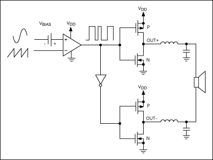
Figure 1. Traditional pulse width modulation topology
Spread-spectrum modulation amplifier topology has a method that can replace this expensive large-size LC filter scheme, that is to improve the switching process, so that the amplifier maintains high efficiency while reducing EMI. Maxim's Class D amplifier does exactly this. This Class D amplifier uses a unique, patented spread-spectrum modulation mode to widen wideband spectral components, thereby minimizing EMI radiated by speakers and cables. Figure 2 shows the topology of this class-D amplifier through Maxim's MAX9700.
Maxim's Class D amplifier modulation scheme uses an internally generated sawtooth wave and uses a complementary signal pair at the input. If there is no complementary input signal, a differential input will be generated inside the IC.
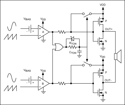
Figure 2. Mono Class D amplifier topology
The comparator monitors the input of the class D amplifier and compares the complementary input voltage with the sawtooth wave. When the amplitude of the sawtooth wave exceeds the input voltage, comparator A will output a low level, pulling the corresponding Class D output (OUT +) high to VDD. When the amplitude of the sawtooth wave exceeds its input voltage, Comparator B will also output a low level, also pulling the corresponding Class D output (OUT-) to VDD. After both Class D outputs are pulled high, a timer at the output of the NOR gate starts to time. The time constant is tau, which is equivalent to 1 / (RTON * CTON). After the fixed time (tau) ends, both Class D outputs are pulled down to GND, and both comparators are reset. This process produces a minimum pulse width tON (MIN) at the output of the second comparator. As the input voltage increases or decreases, the pulse duration of one of the outputs (the first comparator triggers a toggle) increases, while the pulse duration of the other output remains at tON (MIN), resulting in two The net voltage at the terminal (VOUT +-VOUT-) changes.
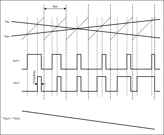
Figure 3. In FFM mode, Maxim's Class D BTL amplifier outputs the input signal
Fixed frequency modulation and spread spectrum modulation Maxim's Class D amplifier uses two modulation modes: (1) fixed frequency modulation (FFM) mode; (2) spread spectrum modulation mode. In FFM mode (Figure 3), the period of the sawtooth wave remains unchanged, which is the same as the traditional PWM scheme. In the spread spectrum modulation mode (Figure 4), the period of the sawtooth wave will change from cycle to cycle (change range up to ± 10%). Figure 4 exaggerates the periodic variation of the sawtooth wave to better show its effect.
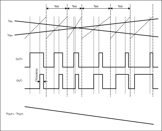
Figure 4. In the spread spectrum modulation mode, Maxim's Class D BTL amplifier outputs the input signal
In the spread spectrum modulation mode, the cycle-by-cycle variation of its period can reduce the spectral energy at the fundamental frequency (fo ± 10%) while expanding the harmonic components within a specific bandwidth (nfo ± 10%, n is a positive integer). At this time, a large amount of spectral energy is not concentrated at each multiple of the switching frequency, but widened within a bandwidth that increases with frequency. After the frequency exceeds a few megahertz, the broadband spectrum looks like white noise, thus achieving the purpose of reducing EMI. In FFM mode, the energy is contained in a narrower frequency band and has a higher peak value (Figure 5a). In the spread spectrum modulation mode, the energy is contained in a wider frequency band, and the peak energy is also reduced (Figure 5b). Note that the third harmonic in Figure 5b is almost covered by the noise floor.
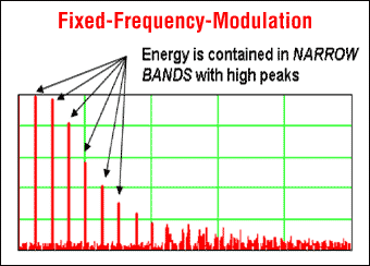
Figure 5a. Maxim's FFM mode
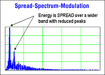
Figure 5b. Maxim's spread spectrum modulation mode
Spread-spectrum modulation mode minimizes EMI radiation. Maxim ’s spread-spectrum modulation technology allows Class D amplifiers to truly “free filters†as long as the speaker cable is not too long. Traditional PWM architectures usually require large-size output LC filters to ensure that consumer products using Class D amplifiers can meet EMI specifications. Maxim's proprietary spread-spectrum modulation technology reduces the emissions of Class D amplifiers, so the output does not require filtering or only the smallest filtering components to meet EMI specifications (see Appendix).
The EMI specification requires that end products must pass existing quasi-peak detection limits—such as those set by CE (European Community, European Standard) and FCC (Federal Communications Commission, American Standard) to ensure the lowest level of electromagnetic interference. According to the definition of these agencies, electromagnetic interference can interrupt, hinder or reduce the effective performance of electronic and / or electrical equipment. In quasi-peak detection, the measured signal level is measured by the repetition frequency of the signal spectrum components. The lower the repetition frequency, the lower the quasi-peak reading. ¹
Spread spectrum modulation makes full use of the average characteristic of quasi-peak detection, thereby greatly reducing the measurement results of EMI (Table 1). In the spread spectrum modulation mode, the peak fundamental frequency of a Class D amplifier varies randomly within a certain range—usually within ± 10% of its basic switching frequency. Assuming that the analyzer uses a 120kHz resolution bandwidth for quasi-peak detection, the switching energy will only appear at any single center frequency for a period of time except for the fundamental frequency of the switching frequency and several higher harmonics.
Table 1. Radiation data for MAX9759 (MAX9759EVKIT, using a 3 "twisted pair speaker cable and" no filter "in spread spectrum modulation mode)

Conclusion The approximate rail-to-rail switching characteristics and fast switching frequency of Class D amplifiers will produce strong RF radiation and interference. Before sound-generating devices such as speakers reproduce audio content, it is generally necessary to use a large and expensive LC filter to reduce such high-frequency interference. But now, if you use an effective PCB layout and short speaker cables, Maxim's spread spectrum modulation technology can truly achieve "filterless" work in low-power applications.
¹For more details on quasi-peak detection, please refer to Reference PublicaTIon 16 published by the International Special Committee on Radio Interference (CISPR) of the International Electrotechnical Commission.
Appendix Overview of Filtering Topologies There are three types of filter topologies for Class D power amplifiers: (1) FB-C, ferrite beads and capacitors; (2) LC, inductance and capacitors; and (3) “no filter ". Which filtering technology should be selected for a particular design depends on the speaker cable length and PCB layout of the application. The following are the advantages and disadvantages of these three filter topologies:
FB-C filtering If the speaker cable length is moderate, FB-C filtering is sufficient to meet EMI restrictions. Compared with LC filtering, the FB-C filtering scheme is more streamlined and more cost-effective. However, since it can only take effect when the frequency is greater than 10MHz, the application range of FB-C filtering is greatly restricted. Moreover, in the case of frequencies below 10MHz, if the speaker cable routing is unreasonable, it will also lead to excessive conducted radiation.
In contrast, LC filtering can start to suppress at a frequency of about 30kHz. When the cable used in a design is long and the PCB layout is not very good, LC filtering is undoubtedly a "safe" option. However, LC filtering requires expensive and bulky external components, which is obviously not suitable for portable equipment. Moreover, when the frequency is greater than 30MHz, the main inductance will self-resonate and additional components will be needed to suppress electromagnetic interference.
"Filterless" filtering The "filterless" amplifier topology is the most cost-effective solution because it eliminates the need for additional filtering components. When using short twisted pair speaker cables, Class D amplifiers can fully meet the electromagnetic compatibility standards. However, as with FB-C filtering, if the speaker cable routing is unreasonable, there may be excessive conducted radiation. It should also be noted that Maxim's Class D amplifiers can also achieve "filterless" operation, as long as the speaker is an inductive load at the amplifier's switching frequency. When the output voltage is converted, the large inductance value at the conversion frequency can keep the overload current relatively constant.
General Features
Stable Quality & High Reliability
Starlight battery is well-known for its stable and reliable performance.Starlight batteries are easy to maintain; thus,permitting a safe and proper operation of theequipment that the battery powers. The battery can withstand overcharge, over discharge,vibration, and shock.It is also capable of extended storage.
Sealed Construction
Starligh's unique construction and sealing technique guarantees that no electrolyte leakage can occur from the terminals or case of any Starlight's battery. Thisfeature insures safe and efficient operation of our batteries in any position. our batteries are classified as "Non-Spillable" and will meet all requirements of the International Air Transportation Association.
Long Service Life, Float or Cyclic
The Starlight Vrla Battery has a long life in float or cyclic service. The expected life of float service is 18 years @ 25℃.
Maintenance-Free Operation
During the expected float service life of Starlight batteries, there is no need to check the specific gravity of the electrolyte, or add water. In fact, there is no provision for these maintenance functions.
Low Pressure Venting System
Starlight batteries are equipped with a safe low pressure venting system,which operates from 1 psi to 6 psi.The venting system is designed to release excess gas in the event that the gas pressure rises to a level above the normal rate.Afterwards,the venting system automatically re-seals itself when the gas pressure level returns its normal rate.This feature prevents excessive build up of gas in the batteries. This low pressure venting system, coupled with the extraordinarily high recombination efficiency, make Starlight batteries the safest Vrla Batteries available.
Heavy Duty Grids
The heavy-duty lead calcium-alloy grids in Starlight batteries provide an extra margin of performance and service life in both float and cyclic applications, even in conditions of deep discharge.
Low Self Discharge
Because of the use of Lead Calcium grids alloy, Starlight VRLA battery can be stored for long periods of time without recharge.
Main Applications:
Alarm Systems;Cable Television;Medical Equipment;Communications Equipment;Micro Processor Based Office Machines;Control Equipment;Portable Cine & Video Lights;Computers;Power Tools;Electronic Cash Registers;Solar Powered Systems;Electronic Test Equipment;Telecommunications Systems;Television & Video Recorders;Emergency Lighting Systems;Toys;Fire & Security Systems;Uninterruptible Power Supplies;Geophysical Equipment;Vending Machines.Middle Sized Vrla Batteries,Middle Size Vrla Battery,12V4Ah Vrla Battery,Lead Acid Battery
Starlight Power Industrial Company Limited , https://www.starlite-power.com