0 Preface
This article refers to the address: http://
The early electric vehicle anti-theft equipment was mainly a mechanical anti-theft lock. It mainly relied on locking the wheel and the handlebar to achieve the purpose of anti-theft, but only the anti-theft did not alarm. In order to overcome the shortcomings of the mechanical lock only the anti-theft alarm, the electronic alarm anti-theft device came into being. It mainly relies on the vibration of the car body to trigger the sound and vibration alarm function to achieve the purpose of anti-theft. However, the traditional electronic burglar alarm is less reliable. Only the vehicle itself sounds an alarm, and the owner sometimes cannot hear it. Therefore, we need a new type of burglar alarm so that they can get the news in the first time so as to take measures to stop the theft case as soon as possible, so as to effectively protect personal property.
1 Design master plan
This design uses AT89S51 single-chip microcomputer and wireless transceiver module as the core of control and signal transmission of the new alarm, and encodes and decodes the signal with the coding and decoding chip (SC2262\SC2272-M4). When the lock button of the handheld remote control is pressed, the relay connected in series with the lock circuit is disconnected, and the vehicle alarm is in an anti-theft state. When the electric vehicle is subjected to a slight vibration by the displacement sensor or the human body is close to the electric vehicle When the battery is sounded, the alarm signal is sent to the remote controller within 200 m to 300 m by two different signals, so that the indicator of the remote controller lights up, and the vibrator and buzzer work to send an alarm signal. At the same time, the on-board alarm sounds automatically after the alarm sounds for 15 seconds, and is reset to the anti-theft state.
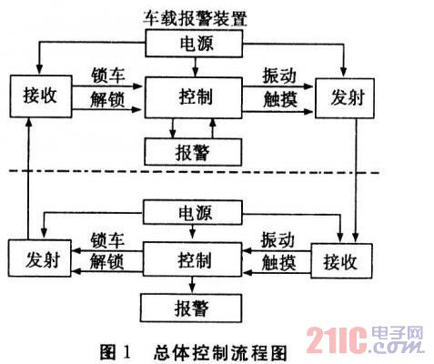
In the anti-theft state, the battery is touched by the human body in time, and the car alarm sends an alarm signal to the remote controller, and the remote controller will respond accordingly.
When unlocking, press the unlock button of the handheld remote control, the car alarm is in the non-working state, and the relay is closed.
2 hardware circuit design
2.1 Handheld remote control circuit
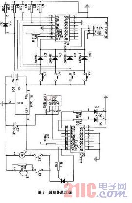
The principle of the handheld remote control is shown in Figure 2. The circuit is composed of a transmitting and receiving alarm circuit, and the transmitting circuit is composed of a transmitting module V1 and a coding chip U1. U1, that is, the 1-8 pin of SC2262 is tri-state address coding. Here we ground the 7-pin of SC2262, and the decoder chip SC2262 of the receiving circuit of the vehicle alarm device is also set to 7-pin grounding, otherwise it cannot be decoded; the receiving circuit is received by the module. V2 and decoder chip U2 are composed of SC2272. Here we set the 1-8-pin tri-state address code of SC2272 to 1, 2, and 7 feet to ground. The transmitting circuit of the corresponding in-vehicle alarm device also sets the three-state address code to the ground of 1, 2, and 7. The alarm circuit consists of a vibrator J2, a buzzer and two LEDs of different colors, D5 and D6. The power supplies are 9 V and 5 V, respectively. The 9 V is directly supplied to the transmitting circuit, and the 9 V is reduced to 5 V via the 7805 to supply the receiving circuit and the alarm circuit.
2.2 Vehicle device schematic
The principle of the vehicle-mounted device is shown in Figure 3. When the SD button is pressed during parking, the received signal of the vehicle receiving module is decoded, and the MCU detects P1. The O port has a high level, and the entire alarm system is in a waiting state, and the speaker emits a short beep.
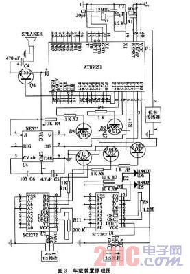
When the car body is slightly shaken, it will be detected by the displacement sensor and generate a weak electric signal to the P1.3 port of the MCU. After the processing and analysis of the MCU, the audio signal is output on the P1.7 port to make the speaker work to sound an alarm. At the same time, the 10th foot of the SC2262 has a high level, and the vehicle transmitting circuit is powered and sends an alarm signal to the remote controller. The remote control receiving module receives the signal input 14 feet for decoding, and simultaneously outputs a high level at 11 and 17 feet, D6 flashes and VT turns on, and the buzzer and vibrator work to issue an alarm.
When a human body touches the lead wire from the trigger end 2 (the second leg of the 555), the clutter signal voltage induced by the human body is added from C2 to the trigger end of the 555, so that the output of the 555 changes from low to high level, 3 The pin is converted to a high level output drive current. Simultaneously. When the 555 pin 7 is internally cut off, the power supply charges C through R. When the voltage on the capacitor C1 rises to 2/3 of the power supply voltage, the 555 pin 7 turns on to discharge C1, so that the output of the third pin changes from a high level. Go back low. The 3-pin output high point is sent to the P1.4 port. After the processing and analysis of the MCU, the audio signal is output on the P1.7 port to make the speaker work to sound an alarm. At the same time, the SC2262 ll foot has a high point, and the vehicle transmitting circuit is powered. Send an alarm signal to the remote control. The remote control receiving module receives the signal input 14 feet for decoding, and simultaneously outputs a high level at 11 and 17 feet, D7 flashes and VT turns on, and the buzzer and vibrator work to issue an alarm.
When the SA of the remote control is pressed, the high-brightness LED illuminates in the dark for illumination, and the high-power input 10-pin code is sent to the vehicle receiving module. After receiving the signal, the vehicle receiving module decodes the decoder and outputs a high level to the P1.1 port of the MCU in the 11th pin of the SC2272. After internal processing, the speaker emits a prompt sound.
When SC is pressed, the high level input ll pin is encoded by the encoding chip and sent to the vehicle receiving module. After receiving the signal, the vehicle receiving module sends the signal to the MCU, and after processing and analysis, the entire alarm system is turned off. The relay K is electrically operated, and the electric vehicle is self-starting.
2.3 Design of battery anti-theft circuit
The touch alarm method is a touch alarm delay circuit based on a 555 integrated circuit. When there is a human body contact or close to the trigger end, a high level is output to make the alarm circuit work, and the trigger end is a wire. Just put it on the handle of the battery case, it is convenient and practical to install.
3 software design
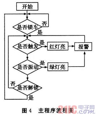
The main program mainly completes the following tasks: (1) Initialization. Set the working mode of the programmable chip and initialize the working parameter area in the memory. (2) Read the key value when there is a typing operation, and jump to the subroutine of the corresponding function. (3) After the subroutine is executed, return to the main loop and wait for the next typing.
4 Conclusion
This design has been tested to achieve the following features:
(1) The alarm signal can be transmitted to the owner in a wireless manner, which is concealed and safe, and the monitoring range is increased.
(2) The alarm signal can be selected from vibration or buzzer mode, which is more user-friendly and convenient for users.
(3) When the vehicle and battery are stolen, the alarm signal is transmitted in two ways, the operation is simple, stable and reliable, and the alarm signal can be received in the range of 200 m to 300 m, and the intelligence is greatly improved.
Short Description:P2mm Indoor LED Module,256mmx128mm P2mm Indoor LED Panel with 128x64 pixels. Model:ERALED-P2-Indoor-128X64; 5 Years Warranty with NICHIA/CREE/NATIONSTAR/EPISTAR/SILAN gold wires LED lamps,1.6cm thickness PCB,MBI5153 Driving IC ;UL,CE,RoHS,FCC,3C,ISO Approved;
Fine pitch Indoor LED Module
256x128mm,128x64 pixels RGB full color SMD UHD P2mm Indoor Led Display Module |
||
|
Module Specifications |
||
|
1 |
Pixel Pitch |
2mm |
|
2 |
Pixel Configuration |
SMD3in1 |
|
3 |
Module Resolution |
128x64 pixels |
|
4 |
Module Pixles |
25,000 pixels |
|
5 |
Module Size |
256x128mm |
|
Specifications |
||
|
1 |
Screen Brightness |
≥1000cd/m2 |
|
2 |
Driving Method |
1/32 scan |
|
3 |
Mini Viewing Distance |
2m |
|
4 |
Max. Power Consumption |
750W/m2 |
|
5 |
Average Power Consumption |
320W/m2 |
|
6 |
Gray Level |
14bits input, 4096 levels(212) |
|
7 |
Display Color |
16M |
|
8 |
Frame Frequency |
≥60Hz |
|
9 |
Refresh Frequency |
≥1920Hz |
|
10 |
Uninterrupted Working Hours |
≥72 hours |
|
11 |
Screen Life-span |
≥100,000 hours |
|
12 |
MTBF |
≥5,000 hours |
|
13 |
Discrete Blind Spot Rate |
<1/10000 |
|
14 |
Continuous Blind Spot Rate |
None |
|
15 |
Blind Spot Rate |
<1/10000 |
|
16 |
Screen Plainness |
<±1mm |
|
17 |
Power Supply Mode |
AC220±10% 50Hz/AC110±10% 60Hz |
|
18 |
Environment Temperature & Humidity |
Temperature:-20 Celsius~+60 Celsius |
|
19 |
Control Mode |
Synchronous display with control PC by DVI |
|
20 |
Control System |
DVI video card + full color control card + fiber system( optional) |
|
21 |
Display Content |
Video, DVD, VCD, TV, picture, cartoon, graphics, texts.etc. |
|
22 |
Interface |
Standard Ethernet |
|
23 |
Transmission Distance |
Multi mode fiber <500m, single mode fiber <30km,internet cable <100m |

Fine pitch Indoor Led Module
High Power Led Module,Soft Flexible Led Display Screen,Pitch Led Display Screen,Curved Led Display Screen
Shenzhen Joy LED Display Co., Ltd. , https://www.joe-led.com