1 Introduction
The CAN bus is the abbreviation of Control Area Network, which was first proposed by German BOSCH company. Because of its high transmission rate, strong anti-interference ability, and convenient hardware connection, it is very suitable for use in automotive systems and solves the problem of data exchange between many test and control instruments.
This article refers to the address: http://
2 Introduction to Intelligent Vehicle System Smart car is mainly used in the field environment. It can make global path planning according to the map information according to the preset instructions of the person, and constantly perceive the surrounding environment information during the process of travel, and independently develop Various decisions lead you to safely exercise and complete the corresponding planning and operational tasks.
In addition to the various functions of ordinary cars, it also increases the position of the car body, measures the direction of the car head, and controls the car to carry out wireless communication with the base in the direction of the antenna. With so much information, if the internal data exchange is completely adopted by the RS-232 bus, it is obviously not enough. Therefore, it is a matter of course to use the CAN bus as a channel for internal data transmission.
3 system design
3.1 Overview The control system of a smart car consists of a lower-level machine system that is responsible for the detection and calculation functions and a host computer system that is responsible for the control display function. Figure 1 is a functional block diagram of the system.
The modules of the lower computer system and their functions:
〇 GPS data acquisition module to measure the current position of the car.
The magnetic compass data acquisition module is used to measure the direction of the front.
Wang Wei, master student, main research direction: computer control and intelligent traffic 〇 stepper motor control module, used to drive the rotation of the directional antenna.
〇Stepping motor rotation angle limiting module is used to measure the angle of the directional antenna relative to the front of the vehicle and to prevent the winding of the line caused by the excessive rotation angle of the stepping motor in one direction.
〇CAN module.
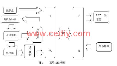
Note: The potentiometer in Figure 1 is used to measure the angle that the stepper motor rotates, convert its output level into a frequency signal and send it to the lower computer. The CAN bus uses a common twisted pair as its transmission medium.
The modules of the host computer system and their functions:
〇 LCD module, used to display various data transmitted by the lower computer.
〇 Simple keyboard input module, through the 8-key keyboard to complete some simple control of the lower computer.
〇CAN module.
The communication between the upper computer and the lower computer is completed by the CAN module and the CAN bus. Among them, the data to be transmitted to the upper computer by the lower computer has the current GPS coordinates of the car, the current direction of the front, the angle of the directed antenna relative to the front of the vehicle; the data to be transmitted to the lower computer by the upper computer, the GPS coordinates of the base, manual The direction and angle of rotation of the motor in mode.
3.2 Hardware Implementation The system upper and lower computer adopts PIC18F258 single-chip microcomputer. The single-chip microcomputer has its own CAN transceiver interface. Its pin is shown in Figure 2. The CAN module is relatively independent, and its main features are as follows:
〇 Pass the ISO CAN standard test.
〇 Execute CAN protocol: CAN1.2 CAN2.0A CAN2.0B.
〇 Standard and extended data models.
〇 0-8 digits of data length.
〇 Programmable rate up to 1M bps.
〇 2 data receive buffers 〇 6 full receive filters, 2 for high priority buffers, and 4 for low priority buffers.
〇 2 full receive maskers.
〇3 priority transmission buffers In this system, the upper computer and its peripheral keyboard and LCD display are connected through a standard parallel I/O bus. The lower computer and its peripheral GPS receiver, magnetic compass and motor driver pass RS-232. The serial bus is connected and will not be described in detail here. Figure 3 is a hardware diagram of the CAN communication module. 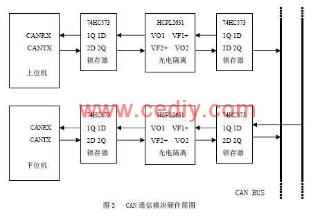
Since the output current of the MCU is relatively weak, it is difficult to drive the opto-isolator. For the sake of safety, the signal input photocoupler must be latched by the 74HC573; also to increase the signal driving capability, the isolated signal is again latched by the 74HC573.
The use of the single chip does not require the expansion of the CAN bus module, which simplifies the hardware design and improves the operating efficiency.
3.3 Software Implementation
The CAN module of the PIC18F258 comes with a number of control and data registers. For convenience, they can be classified as follows:
〇Control and Status Register 〇Transmit Buffer Register 〇Receive Buffer Register 〇Baud Rate Control Register 〇I/O Control Register 〇 Interrupt Flag and Control Register CAN Module can work in 6 modes, configuration mode, disable mode, normal working mode , listening mode, self-loop mode, error recognition mode. The system involves two modes, configuration mode and normal working mode.
First, in the configuration mode, the control and status registers, baud rate control register, I/O control register, interrupt flag and control register, receive masker and acceptance filter are set according to system requirements to ensure smooth CAN bus. These registers can only be set in configuration mode. After setting, enter the normal working mode. Both the upper computer and the lower computer open their respective CAN receive interrupts and wait for the data transmitted by the CAN bus. The difference is that the host computer sends a control signal to the bus only when manual intervention is required; and the lower computer sends the collected information to the bus cyclically.
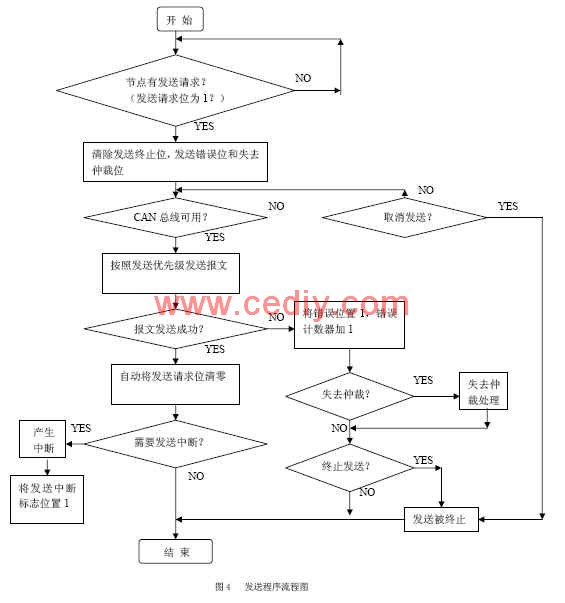
Figure 4 is a flow chart of the CAN module sending data:
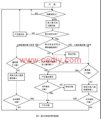
CAN module data reception is realized by interrupt mode, that is, every time a message is transmitted, an interrupt occurs, and then the received data is transferred from the receiving register to the specified storage area and saved, and finally the interrupt is returned.
Figure 5 is a flow chart of the interrupt service routine for receiving data from the lower computer CAN module:
4 About several problems in the design (1) The lower computer sends data cyclically. After each message is sent out, wait for sufficient time before sending the next message. Otherwise, it may happen that the last message is not sent and the next message is loaded. As a result, packets are lost, and even each message cannot be successfully sent. The waiting time is related to the clock frequency of the microprocessor and the baud rate of the message transmission.
(2) Various errors may occur during the transmission of the message, and the CAN protocol provides a mature error checking mechanism. These errors may include: CRC errors, response errors, formal errors, bit errors, padding bit errors, and the causes of these errors vary. For the PIC18F258, the error counter inside the CAN module is incremented by one every time an error occurs. Once the value of the error counter is greater than 255, the bus is turned off. At this time, the CAN bus cannot be used to send and receive data. It will wait for 128 consecutive 11-bit recessive bits and then return to normal. No interruptions are allowed during system operation, so the error counter should be cleared or restored to the extent that the bus is allowed to operate before entering the bus off state.
(3) The data that needs to be transmitted in this system is limited compared to the powerful functions of the CAN bus. However, considering the improvement and expansion of the system in the future, more network nodes will be needed, and more data will be transmitted. Therefore, the system reserves a lot of hardware and software resources for future use.
5 Conclusion The intelligent car system in this paper has expanded its functions on the basis of ordinary automobile systems, involving some technologies in the field of artificial intelligence. The data is transmitted between the upper computer and the lower computer by the CAN bus. The RS-232 interface is only connected to the peripheral detection and control device, and the division of labor is clear, which will not cause the serial bus to be too busy, thus causing data transmission errors.
The communication network formed by CAN bus has strong scalability, high reliability, self-diagnosis and monitoring capability, which not only improves communication quality, but also facilitates software and hardware design. The PIC18F258 MCU used in this example has its own CAN bus interface, which has superior performance and low price, and will inevitably be favored by designers.
The concept of strong electricity is relative to weak electricity. Strong and weak currents are separated by voltage. The working voltage is more than 24V AC is strong, and the following is weak. Strong wires generally refer to transmission wires with an AC voltage of more than 24V. Such as home lights, sockets, etc., the voltage is 110 ~ 220V. Strong wires can also affect nearby communication lines. The following describes the knowledge of strong wire protection.
(1) Different AC frequencies
The frequency of strong electricity is generally 50Hz (Hz), which is called "power frequency", which means the frequency of industrial electricity: the frequency of weak electricity is often high frequency or ultra-high frequency, measured in KHz (kilohertz) and MHz (megahertz).
(2) Different transmission methods
Strong electricity is transmitted on transmission lines, and weak electricity transmission is divided into wired and wireless. The radio transmits electromagnetic waves.
(3) Different power, voltage, and current
Strong electric power in KW (kilowatts), MW (megawatts), voltage in V (volts), KV (kilovolts), current in A (ampere), kA (kiloampere); weak electric power in W (watts) , mW (milliwatts), voltage in V (volt), mV (mV), current in mA (milliampere), uA (microampere), so its circuit can be printed circuit or integrated circuit composition.
There are also high-frequency (hundreds of KHz) and medium-frequency devices in high-voltage power supplies, but the voltage is high and the current is large. Due to the development of modern technology, weak electricity has penetrated into the field of strong electric power, such as power electronic devices, wireless remote control, etc., but these can only be regarded as the weak electric control part in strong electric power, and it is still different from the controlled strong electric power.
According to the basic principle of weak electricity transmission signals and strong electric conduction, we can easily distinguish between strong electricity and weak electricity. For example, although electric shavers, flashlights, etc., use only two dry batteries (3V), we cannot think that they are weak because the voltage and current of the appliances are small, because they conduct electricity rather than signals, so they should be classified as strong. class.
From the above description, the relationship between the four can be roughly stated as follows:
High voltage must include strong electricity, and high voltage does not necessarily belong to high pressure.
Low voltage must include weak electricity, weak electricity must belong to low pressure;
Low voltage is not necessarily strong, and strong power is not necessarily low pressure.
The use of strong electricity
Strong electricity generally refers to the mains power system\lighting system and other power supply and distribution systems, including air conditioning lines, lighting lines, outlet lines, power lines, high-voltage lines and the like. There are two types of weak electricity: one is the state-designed safe voltage level and control voltage and other low-voltage electric energy, and there are AC and DC points, such as 24V DC control power supply, or standby power supply for emergency lighting. The other is information sources that carry information such as voice, images, and data, such as audio, video lines, network lines, and telephone lines. DC voltages are generally within 36V. Electrical appliances such as telephones, computers, televisions (cable television lines), audio equipment (output lines), broadcasting systems, and building automation (such as access control and security) in household electrical appliances are all weak electrical equipment.
In power systems, voltages below 36V are called safe voltages, voltages below 1kv are called low voltages, voltages above 1kv are called high voltages, and lines that directly supply power to users are called distribution lines, such as user voltages are 380/220v, It is called a low-voltage distribution line, which is the strong electricity in home decoration (because it is the highest voltage for home use). Strong electric generally refers to direct current voltage above 24V. Such as home lights, sockets, etc., voltage 110V ~ 220V. Electrical appliances for home lighting, electric water heaters, heaters, refrigerators, televisions, air conditioners, audio equipment, etc. are all electric equipment.
High Current Cable,Pvc Insulated Copper Core Wire,Bvr Electric Cable,Bv Power Cable
Jiangsu QiSheng Cable Co., Ltd. , http://www.shuaihe-cable.com