introduction
This article refers to the address: http://
The application of TPMS on heavy-duty vehicles has been slow to start in the field of automotive electronics at home and abroad. In fact, heavy vehicles have a higher probability of bursting due to the larger load capacity. Nowadays, there are so many kinds of automobile safety products that the communication between them is complicated and the resources are wasted. This paper proposes a new implementation method for integrating the safety accessories such as TPMS and automobile drive recorder on heavy vehicles, and replaces the previous one with the unified coordination and management of an electronic control unit. A plurality of automobile safety products are separately controlled to form a vehicle safety electronic control system. The whole vehicle safety electronic control system consists of a tire pressure monitoring system, a reversing radar device, a vehicle driving recorder, etc. All devices are connected to the CAN bus and share the dashboard display. It focuses on the implementation principle of TPMS. The software for receiving the display part is managed by the micro real-time operating system uCOS-II disclosed by the source code, so that the real-time performance and reliability of the whole system are further improved.
1 Scheme selection
Large trucks can use up to 36 TPMS transmitters, so the signals of the back dozens of wheels must be relayed and relayed. Signal transponders must be added, because the distance of the big trucks from the rear wheels to the cab is about 10 meters. If the semi-trailer is longer and the transmission power of the TPMS exceeds 10 dBm, then the entire product and system are subject to the control of the Radio Regulation Committee. There are two methods for signal relay: First, wireless transceiver, that is, wirelessly receiving the RF signal of the transmitting module, and then transmitting it to the receiving module in a wireless manner. 2. The radio frequency signal of the wireless receiving and transmitting module is transmitted to the receiving module through the CAN bus.
The wireless transceiver solution, the relay module is easy to install, but has the disadvantages of low reliability and easy crosstalk between RF signals between modules. Compared with the wireless transceiver solution, the CAN bus transmission has a high communication rate and a very high reliability. At the same time, the external wiring is convenient, flexible, and low in cost, and is very suitable for the application of the relay module. Therefore, the tire pressure monitoring system adopts the CAN bus relay signal scheme.
2 TPMS system structure
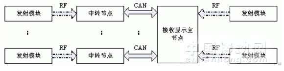
Figure 1 Schematic diagram of TPMS system structure
The TPMS consists of three functional modules: the radio frequency transmitting module, the signal relay node, and the receiving display master node. Figure 1 shows the structure of the TPMS system. The transmitting module monitors the tire pressure, temperature, battery power and other information. The RF2 microcontroller integrated with the RF chip transmits the information in the form of electromagnetic waves. The relay module processes the received RF signals. It is transmitted to the receiving display module through the CAN bus; the receiving display module receives the RF signals transmitted by the two front wheels with a short distance on the one hand, and receives the signals such as the tire pressure temperature transmitted by the relay module through the CAN on the other hand. CAN adopts short frame transmission, which has short transmission time, low probability of interference and high reliability. It also facilitates real-time transmission. The launching module is mounted on the valve nozzle outside the tire and is reinforced with a metal outer casing. The relay module and the receiving display module are respectively mounted on a fixed position away from the receiving display module near the tire and on the cab dashboard.
3 system function module design
3.1 Transmitter module

Figure 2 Sensor connection circuit of the transmitting module
The transmitting module is installed in the tire, and the connecting portion of the measuring and detecting portion is as shown in FIG. 2 . The sensor uses Infineon's silicon piezoresistive pressure sensor SP12T, which has a tire pressure measurement range of 50 to 1400KPa. It is a sensor specially designed for heavy-duty vehicles. The SP12T integrates a pressure sensor, temperature sensor and voltage sensor to provide accurate tire status information. The 908RF2 uses an internal oscillator to provide the operating clock of this microcontroller to enhance immunity to interference. The SP12T and 908RF2 are connected through an SPI interface. The 908RF2 integrates the MC33493, which reduces the board area and cost, and has higher reliability. The transmission adopts Manchester coding mode, FSK modulation mode, and the transmission frequency is 433.92 MHz.
3.2 transit node
The relay module is configured to process and forward the information received from the transmitting module to the receiving module, and function as a signal relay. The transfer module is mainly composed of the chip MC33594 and the low-cost single chip MC68HC908GZ16 with CAN interface. The 33594 transmits the received RF number to the GZ16 in the SPI protocol transmission format, and the GZ16 transmits the data information to the receiving module in the CAN protocol transmission format.

3.3 receiving display master node
The receiving module main chip adopts FREESCALE 16-bit single-chip MC9S12DP256, which has 5 CAN interfaces, 2 serial ports, 8 enhanced timers and other rich internal peripherals, leaving a large space for system upgrade. The CAN0 interface is used to receive information sent by the relay module. The receiving chip MC33594 receives the RF signals of the two front wheels which are close to each other, and decodes them and sends them to the MC9S12DP256 in the SPI transmission protocol. The CAN interface chip uses MAXIM's MAX3050 to provide differential transmit capability for the bus and differential receive capability for the CAN controller.
4 Software implementation based on uCOS-II
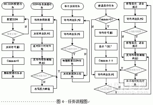
The transmitting module receives a small amount of relay module code, and the software is written in the traditional front-back system mode, which saves time and occupies the minimum memory. The main program flow of the software of the transmitting module is very simple. After power-on, the system enters the system initialization and enters the shutdown state. Wait for the SP12T's timed wakeup interrupt. The entire reception shows a total of four tasks, three interruptions, on the TPMS section. The four tasks include the MC33594 configuration task, the MC33594 receives the RF data task, the LCD display task, and the serial port sends the data task. The corresponding task priorities are 6, 9, 12, and 15, respectively. The three interrupts are the serial port receiving interrupt, the CAN bus receiving interrupt, and the key interrupt. The system uses a semaphore, two mailbox messages, and two message queues for communication between tasks. The specific software flow is shown in Figure 4.
5 Conclusion
The design hardware combines the highly reliable CAN bus transmission with the wireless transmission of the direct tire pressure monitoring system. The CAN transmission avoids the mutual interference caused by the wireless relay module. The software combines the traditional front-back system programming method with the portable programming method of the portable system, and the advantages are complementary, and the strengths and weaknesses are avoided. The system fully realizes all the functions of tire pressure monitoring and has a wide range of practical application markets. The overall reliability of the system is high, the stability is good, the cost is low, and it is convenient for transplantation, and it is convenient to add other functions.
With a professional R & D team, the company has applied for 296 patents and 231 granted patents, including 43 invention patents. With a high technical qualification, the company has participated in the development of 14 national and industrial standards and organized several industry technical interchange meetings

Extractor Hood,Durable Swift Cooker Hoods,Kitchen Extractor Hood,Auto Clean Range Hoods
xunda science&technology group co.ltd , http://www.xundatec.com