In this design, a TVS diode is used. If you didn't pay much attention to the TVS tube in your previous designs, let's take a closer look at its function and characteristics through this detailed explanation. The TVS, or Transient Voltage Suppressor, is a protective device that works similarly to a Zener diode but with a much faster response time. It is essentially a diode-based component that uses reverse breakdown to stabilize voltage. However, unlike a Zener diode, the TVS can react within sub-nanoseconds when exposed to high-energy transient voltages. This rapid response allows it to switch from a high-impedance state to a low-impedance state almost instantly, effectively clamping the voltage and absorbing surge energy. This makes it ideal for protecting sensitive electronic components from voltage spikes.
Comparing TVS with Zener diodes, both have similar functions in limiting voltage across their terminals and have comparable long-term current handling capabilities. However, there are key differences. First, Zener diodes offer more precise voltage regulation, while TVS devices operate within a range. Second, Zener diodes can only handle small surge currents, typically in the range of milliamps, whereas TVS can manage several hundred amperes. Third, Zener diodes rely on tunneling or avalanche effects, while TVS mainly uses avalanche effect. Fourth, Zener diodes are used for voltage regulation, while TVS is designed for transient voltage protection. Lastly, Zener diodes usually have lower voltage ratings (3.3V–75V), while TVS can go up to 550V. Also, TVS has a significantly faster response time—often less than 1 picosecond—which makes it more suitable for high-speed protection applications.
Now that we've covered the basic principle, let's move on to some key parameters of the TVS tube. These values are clearly listed in the datasheet and provide a better understanding of how the device performs in real-world conditions.
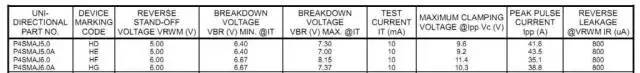
The first two columns in the table are device-specific and not essential for general use. The Reverse Stand-Off Voltage (VRWM) is the maximum voltage the TVS can withstand without conducting. This ensures minimal leakage current during normal operation. The Breakdown Voltage (VBR) is the voltage at which the TVS enters avalanche breakdown, allowing it to conduct current and clamp the voltage. The Test Current (IT) is the DC current used to measure the breakdown voltage. The Maximum Clamping Voltage (VC) is the highest voltage the TVS will allow during a surge, and it depends on the peak pulse current (IPP). The Peak Pulse Current (IPP) indicates the maximum current the TVS can safely absorb during a short surge event. The Reverse Leakage Current (IR) is the small current that flows through the TVS at VRWM, which should be as low as possible to avoid unnecessary power loss.
Other important parameters include Junction Capacitance (Cj), which affects signal integrity in high-speed circuits, and Insertion Loss, which is often specified for TVS used on high-speed I/O lines. These factors determine whether a TVS is suitable for a particular application. When selecting a TVS, follow these guidelines: the rated reverse stand-off voltage (VWM) should be higher than the circuit’s maximum operating voltage; the minimum breakdown voltage (VBR) should be around 80–90% of VWM; the maximum clamping voltage (VC) must be below the damage threshold of the protected circuit, typically 1.3 times the VBR; and the peak pulse power (PM) must exceed the expected surge power. Finally, ensure the peak pulse current rating is sufficient to handle any potential surges in the circuit.
Logic Gates And Inverters,Circuit Logic Gates And Inverters,Logic Chip Gates And Inverters,Gates And Inverters Logic Output
Shenzhen Kaixuanye Technology Co., Ltd. , https://www.icoilne.com