Feedforward headphones are generally easier to develop because design engineers often do not have to deal with stability issues. However, one of the main drawbacks of this topology is Wind noise because its noise-reduction microphone is directly exposed to the environment. One way to overcome this shortcoming is to use feedback active noise reduction techniques. This article will explain the steps required to design a feedback active noise canceling headphone with ams AS3435.
Equipment review
As with feedforward earphones, feedback headsets also require specific equipment, the most important of which is an audio measurement system that measures frequency response and phase response.
Audio equipment suitable for these measurements includes Audio Precision, Bruel & Kjaer and Soundcheck. A human ear simulator with different types of artificial ears can be used to simulate the acoustic response of the human ear. Head AcousTIcs, Bruel & Kjaer or GRAS products are recommended.
IEC711 couplers commonly used in feedforward in-ear products are not required in this application. In a feedback in-ear system, the placement of the microphone is limited by space. Therefore, 99% of feedback headphones are generally on-ear or over-ear designs. Of course, there are still feedback in-ear designs on the market. In addition to simulating the human ear and audio measurement equipment capable of measuring gain and phase, the remaining devices for feedforward design already include all the requirements for developing feedback active noise canceling headphones. To determine the active noise reduction performance of the headphones, a two-way speaker system (preferably a two-way coaxial speaker) is required to expose the active noise canceling headphones to the noise field for testing.
The last element required to design a feedback active noise canceling headphone is the AS3435 evaluation board (EVB), which includes all the necessary connectors and preamplifiers to meet the needs of earphone acoustics measurements.
How to measure the acoustic characteristics of feedback headphones?
In addition to mechanical components such as cushions and speaker chambers, each active noise canceling headphone requires electroacoustic components such as speakers and active noise canceling microphones. These components are grouped together to determine the frequency and phase response of the headset. Different headphones have different frequency and phase responses, so correct feature measurement is required to optimize the active noise reduction performance of each earphone to achieve maximum bandwidth.
Compared to the feedforward system, the active noise reduction measurement of the feedback system is very simple. All that is required is to measure the open loop between the earphone speaker and the active noise canceling microphone.
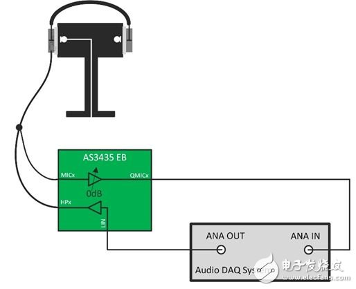
Figure 1: Feedback Headphone Characteristics Measurement
The measuring device includes the Audio DAQ (data capture) system shown in Figure 1, an artificial head and an active noise canceling earphone. The output of the Data AcquisiTIon system is connected to the input of the AS3435 evaluation board. The speaker of the active noise canceling headphone is connected to the headphone amplifier output of the AS3435 evaluation board, and the active noise canceling microphone is connected to the microphone input of the evaluation board. The bias voltage required for the design is provided by the evaluation board, so the microphone connection does not require additional external components.
The last important and necessary connection is the analog audio input from the evaluation board's QMICx pin (microphone preamplifier output) to the DAQ system. The AS3435 evaluation board must be properly configured before the measurement begins. A screenshot of the EV kit software is shown in Figure 2. It is important to set the mic preamp gain to 0 dB so that it can match the ams filter calculation template.
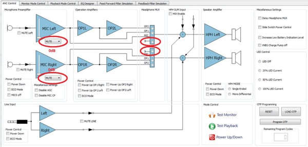
Figure 2: Software configuration for feedback system characteristic measurement
In addition, it is also necessary to set the headset multi-input to the "unconnected" position to help prevent the microphone signal from being fed back to the speaker. Of course, this is required during the active noise reduction operation, not for the measurement of the open loop characteristics.
When the EV kit is properly configured, the DAQ system produces a sinusoidal sweep signal from 20kHz to 20Hz. The DAQ system then measures the gain and phase response of the microphone preamplifier output. This measurement includes all the information needed for the design of the feedback filter.
Active Noise Reduction Filter (ANC Filter) calculation
The active noise reduction filter calculation of the feedback circuit is very simple, and the calculation method is as follows:

The ideal phase response is calculated as follows:
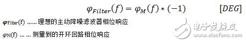
As shown in these equations, the required filter calculation is simply the inverse of the gain and phase response. The calculation can be done with an Excel spreadsheet. This calculation template is available from the AS3435 evaluation kit.
Filter development
The next, and perhaps the most important step in the development process, is the development of active noise reduction filters. Filter calculations to understand the characteristics of active noise canceling headphones mean that this information can be used in the development of active noise reduction filters. The acoustic characteristics of the noise canceling headphones and the filter calculations can be used for the development of ANC filters.
There are many feedback active noise canceling headphones on the market, but most of the designs simply reverse the feedback signal, so the active noise reduction performance is extremely low. Therefore, it is important to grasp the key points in the filter development process, including understanding and understanding the limitations of the system. Experienced engineers can use the Spice simulation tool to design active noise reduction filters. This requires a lot of experience, especially in terms of filter topology and filter calculations. Figure 3 shows an example of an active noise reduction filter.
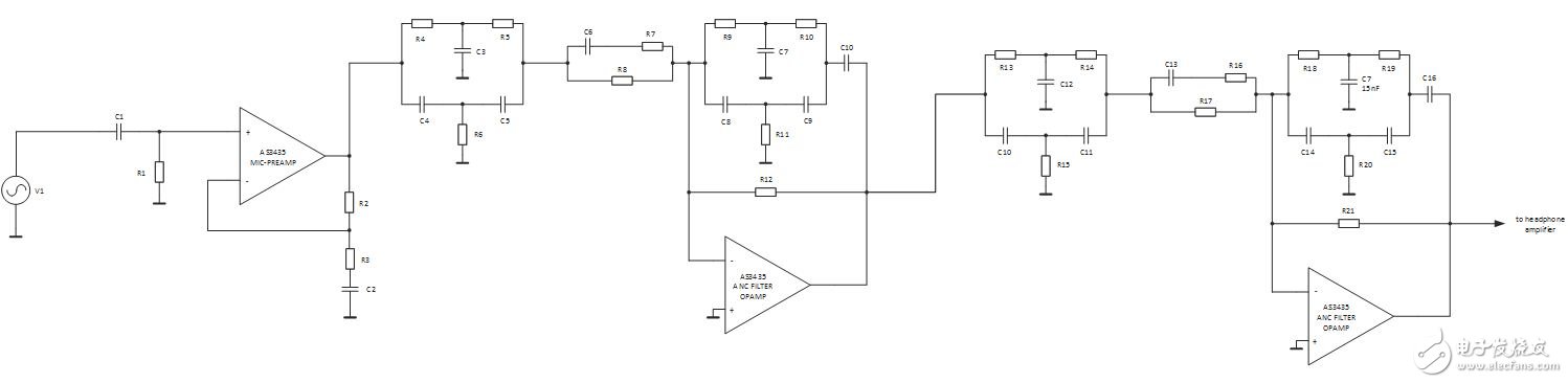
Figure 3: Spice Filter Simulation Example
Shown as a complete active noise reduction signal chain, including an inverting amplifier and RC network, the frequency and gain response of the active noise reduction filter can be designed. To make it easier for engineers to design filters, ams developed a filter simulation tool as part of the AS3435 evaluation software. A screenshot of this simulation tool is shown in Figure 4.
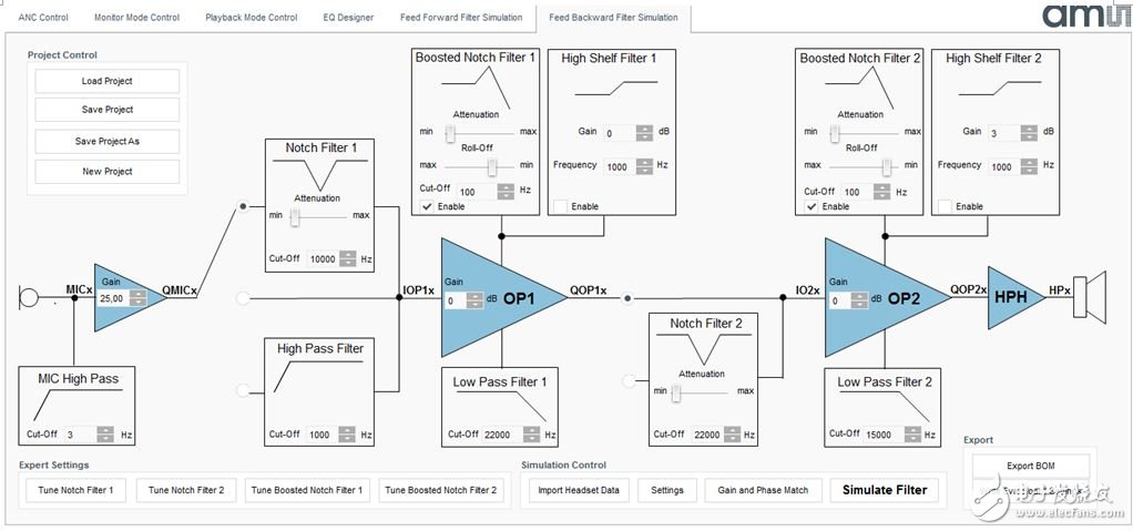
Figure 4: AS3435 Filter Simulation Tool
The tool also uses a spice simulator, but is equipped with a graphical user interface (GUI) that makes filter development much easier, especially for "untrained" design engineers. It helps design engineers define different gain and cutoff frequencies through a predefined set of filter topologies. This system is not as flexible as the spice simulator, allowing the user to define filter topologies as well as resistance and capacitance values, but it is a good starting point and will help design engineers better understand the active noise reduction filter design that may be encountered Difficulties.
The simulation window shown in Figure 5 shows the results of setting the filter simulation in the simulation window. The green curve is the ideal feedback filter, which is the flip of the measured open loop. The blue curve represents the result of the spice simulation. The difference in feedback filter simulation feedforward filter simulations shows that only frequency and phase matching is not enough. In the feedback system, higher gain results in better active noise reduction. However, in a feedforward system, too high gain can not eliminate noise, but will amplify noise. In feedback systems, the focus is usually in the lower frequency range: from 20 Hz to 800 Hz. Based on the acoustic performance of the headphones, the peak of the focus falls within the range of 100 Hz. Higher frequencies are also more difficult to eliminate because it is difficult or impossible to match their phase response. Therefore, it is important to reduce the higher frequencies and avoid system oscillations as much as possible.

Figure 5: Filter Simulation Results
If the gain is too high and the phase mismatch between the simulated filter and the theoretically calculated ideal filter is too large (typ. 120°), the headphones will oscillate. The AS3435 filter simulation software features a stability check function that automatically displays the gain and phase mismatch between the theoretically calculated ANC filter and the simulated ANC filter. The simulation results are shown in Figure 6.
In areas where the phase mismatch is greater than 120° and the gain mismatch is above -12 dB, the tool highlights the focus area with a red frame. In this frequency region, the incidence of oscillation is very high.

Figure 6: Stability check function
In areas with high phase mismatch, the filter design engineer must ensure that the gain is as low as possible. Oscillation generally occurs at high frequencies, but it is also possible to occur near 1 Hz.
Filter verification and active noise reduction testing
This filter can be derived when the design engineer finds that a filter is stable over the entire frequency range. The tool integrates the bill of materials (BOM) output function, and the block parts in the bill of materials are common materials based on the E24 standard. In addition, because the component indicators exactly match the evaluation board, the components in the bill of materials can be soldered directly to the evaluation board.
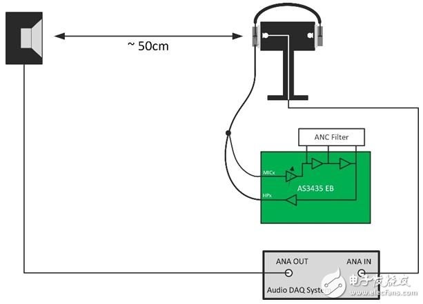
Figure 7: Active noise reduction performance test
The active noise reduction performance test consists of two steps and no phase measurement is required. The earphone is first worn on the artificial head for passive attenuation measurement. Step 2 is similar to step 1, but the AS3435 needs to be turned on, configured according to the feedback application, and the gain of the microphone preamplifier is set according to the simulation result. The noise reduction performance can be calculated according to the two measured data according to the following formula:

The calculation can be done with Excel and the noise reduction curve can be drawn. This noise reduction curve is a very common indicator in the industry.
For the development of active noise canceling headphones using AS3435, related development tools, application notes and templates are available and available upon request.
FTTH Fiber Optic Splice Tray is designed to provide a place to store the fiber cables and splices and prevent them from becoming damaged or being misplaced. It is also called a splice enclosure or splice organizer. This device does not contain any technical functions, and the design is simple. Also, Fiber Optic Tray has a very low price for people to afford. However, the importance of fiber splice tray for protecting fibers is significant. And the skills needed for using a fiber splice tray is not as simple as you think.
Made by industrial high-quality ABS plastic, Fiber Optic Cable Tray is provided to place the fiber splice points and pre-terminated for fiber connectivity. The splice tray expands fiber splice capabilities as well as provides the splicing location for fiber optic cables. It can be put into the fiber distribution frame, fiber splice closure, optic terminal box, etc. Sijee offers different shapes of fiber splice tray with or without termination function. Fiber Optic Tray, Fusion Splice Box, Fiber Optic Cable Tray, Splice Tray Optic Fiber are available.
Applications:
Fiber splice trays are usually placed in the middle of a route where cables are required to be joined or at the termination and patch panel points at the end of the cable runs. Also, splices can be placed in a splice tray which is then placed inside a splice closure for OSP (outside plant) installations or a patch panel box for premises applications. As for indoor application, fiber splice trays are often integrated into patch panels to provide for connections to the fibers.


FTTH Fiber Optic Splice Tray
Fiber Optic Tray,Fusion Splice Box,Fiber Optic Cable Tray,Splice Tray Optic Fiber
Sijee Optical Communication Technology Co.,Ltd , https://www.sijee-optical.com