Introduce a multi-function meter with multiple functions such as voice output, price display, clock display, ticket printing, operating parameter adjustment, and metering data query. The hardware structure and software block diagram of the system are described in the paper.
Keywords: meter; single chip microcomputer; micro printer; IC card
This article refers to the address: http://
Design of a Multi-function Taximeter
LI Yan1, LI Xiaoyu2
(1.College of Mechanical and Electrical Engineering, Central South Un iv ersity,
Changsha 410083, China;
2.Shandong Association of Plant Engineering, Jinan 250011, China)
Changsha 410083, China;
2.Shandong Association of Plant Engineering, Jinan 250011, China)
Abstract: A multi-function taximeter is presented in this paper , which has speech, display, measure functions and can print receipt, inquire da ta, adjust parameter and so on. The hardware circuit and software flowchart are introduced.
Keywords: taximeter; microprocessor; micro printer; IC card
Keywords: taximeter; microprocessor; micro printer; IC card
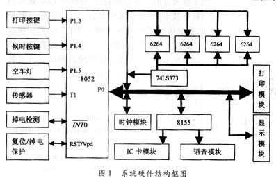
1 system hardware structure and functional characteristics of the system hardware block diagram shown in Figure 1. The external signals that the system needs to input are sensor signals and empty lights. The sensor is connected to the taxi shaft, and a pulse is sent to the wheel to calculate the distance. The empty headlight signal is used to determine if the taxi is in an empty state. The system uses the 8052 as the central CPU unit, which is mainly divided into voice module, display module, clock module, printing module and IC card management module. The following describes the various features of the system.
1.1 Voice Module Considering the miniaturization and intelligence of the meter product, the voice chip adopts the ISDl420 chip with high integration. Its biggest feature is the direct access of analog information by EEPROM without A/D and D/A conversion. . It has a microphone amplifier, automatic gain control clock, speaker driver circuit, etc., and is powered by a +5V power supply.
The interface between the voice module and the main system is shown in Figure 2. The main system is connected to the ISDl420 chip through the PA port of the 8155 expansion chip. In the design process, the fixed speech part (upper and lower vehicle terms) information is first stored in different starting addresses inside the ISDl420. During the operation process, different voice functions are played according to different operating states of the upper and lower vehicles. When the voice chip is working, the system first transfers the main program pointer to the playback processing program, searches for the pronunciation unit in the ISDl420 according to the pronunciation address, and then sends the signal to the speaker to make a sound. After the main CPU completes the sounding program, it immediately transfers to another subroutine. 

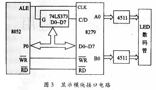
The display module is used to display various detailed operational data of the meter during operation, such as time, unit price, total price, waiting time and mileage. The components used are display interface chip 8279 and LED digital tube, and its interface circuit is shown in Figure 3.
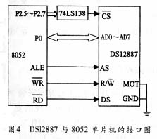
This system uses DSl2887 real-time clock chip. It has its own address latch function, and the interface with the main system 8052 chip is very simple, as shown in Figure 4. AD0 to AD7 are bidirectional address/data multiplexing buses. AS is the address strobe input, under it 
After the power is turned on, the DSl2887 is initialized by software, that is, each register is written with an initial value.
After the power is turned on, the DSl2887 is initialized by software, that is, each register is written with an initial value.
Print taxi invoices, including license plate number, boarding time, drop-off time, waiting time, mileage, unit price, amount and date.
The system is designed with intelligent micro-switching circuit separately: It is connected to the host computer by means of interface board. This feature makes the ticket printing of the meter be functionally integrated with the main system, and can be carried out separately during inspection and maintenance. The micro-printing head used in this system is a model produced by EPSON, Model 15 0II. It is a mechanical dot matrix 4-pin printing mechanism with four horizontally mounted electromagnets on the same carriage. The micro-play uses a separate single-chip system, taking into account the performance requirements of the micro-play itself, using Intel's 8 051 chip. The micro-player is connected to the main MCU through a parallel interface, and its interface diagram is shown in FIG. 5. When the data to be printed appears on the printer I/O0~I/O7, the STB can send data to the printer as long as it goes from high level to low level and then goes from low level to high level. At this time, the printer sets the BUSY line to busy (high level), prohibiting new data input. When the printer takes the data and processes it, the BUSY line is set to idle (low level), and the answer pulse ACK notification system is sent. You can enter the data again. 
The system is designed with intelligent micro-switching circuit separately: It is connected to the host computer by means of interface board. This feature makes the ticket printing of the meter be functionally integrated with the main system, and can be carried out separately during inspection and maintenance. The micro-printing head used in this system is a model produced by EPSON, Model 15 0II. It is a mechanical dot matrix 4-pin printing mechanism with four horizontally mounted electromagnets on the same carriage. The micro-play uses a separate single-chip system, taking into account the performance requirements of the micro-play itself, using Intel's 8 051 chip. The micro-player is connected to the main MCU through a parallel interface, and its interface diagram is shown in FIG. 5. When the data to be printed appears on the printer I/O0~I/O7, the STB can send data to the printer as long as it goes from high level to low level and then goes from low level to high level. At this time, the printer sets the BUSY line to busy (high level), prohibiting new data input. When the printer takes the data and processes it, the BUSY line is set to idle (low level), and the answer pulse ACK notification system is sent. You can enter the data again. 

This function is done by the IC card. Some measurement parameters used in the operation of the meter, such as: day and night unit price, rent mileage, and rent amount, are set in the IC card through the program. At the same time, the IC card is used to store the driver's detailed operational data and IC card control settings to achieve unified management and operational data query.
In this system, the IC card holder is connected to the PC port of the 8155. The specific connection is: the reset port RST of the PCI port card holder, the PC0 port is connected to the clock pulse end CLK of the card holder, the PC2 port is connected to the data input/output terminal I/O of the card holder, and the PC3 port is connected to the VDD end of the card holder.
The IC card is powered by an independent power supply and is controlled by the 8052. When a card is inserted, the IC card is supplied with the required power. If you insert an object such as a bad card or a metal piece that is broken by the power supply and the ground, it will cause a short circuit in the power supply circuit and interfere with the operation of the entire device. IC card independent power supply mode, when the IC card power supply short circuit condition, the power supply regulator is short-circuit protected due to output overload, output low level, when the CPU detects low level, the power supply to the IC card will be interrupted. 
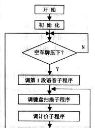

The system software adopts modular design, and the system program is solidified in the internal ROM of the microcontroller. The block diagram of the main program is shown in Figure 6, which contains several subroutines and interrupt service routines. The functions of the subroutine include system initialization, key processing, display, voice and data transmission processing, etc. The interrupt service program includes counting and processing of driving pulses, counting and processing of time, power failure protection processing, printer processing, and the like.
The meter realizes the automatic control of the IC card measurement parameters and the double backup of the key data, so that the accuracy and stability of the driving data are greatly improved. In addition, the meter is composed of high-reliability component devices, with a variety of anti-interference measures, can withstand the test of various bad conditions. The new multi-function meter system has stable performance, small size and low cost, and can well meet the market demand for taxi meter. 
Rj45 Tool,Rj45 Punch Tool,Ez Rj45 Tools,Electrical Wire Crimping Tool
Dongguan Fangbei Electronic Co.,Ltd , http://www.connectorfb.com