RF power amplifiers are widely used in various wireless communication systems, especially in transmitting devices. In base stations, linear power amplifiers account for approximately one-third of the total cost, making their efficient and cost-effective linearization a critical challenge. Research on high-efficiency and high-linearity power amplifiers has become a hot topic, particularly for WCDMA power amplifiers in recent years. Currently, only a few companies in China can produce WCDMA power amplifiers with output power exceeding 10 W, as these amplifiers require higher linearity. Traditional back-off methods result in only a few watts of output, which is insufficient for base stations and is typically limited to small-scale repeaters.
The design of power amplifiers focuses on achieving both high linearity and efficiency. Feedforward structures are a mature solution widely used in modern communication systems. Meanwhile, digital predistortion is considered a promising technique for improving linearity. As communication technologies evolve, efficiency has also gained more attention. The Doherty amplifier structure is regarded as one of the most promising approaches for enhancing efficiency. Combining feedforward or digital predistortion with the Doherty structure offers significant potential for performance improvements.
### 1. Doherty Power Amplifier Design
#### 1.1 Overview of Doherty Power Amplifier Principle
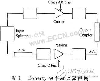
The Doherty architecture consists of two power amplifiers: a main amplifier and an auxiliary amplifier. The main amplifier operates in class B or AB, while the auxiliary amplifier works in class C. Unlike traditional designs, the main amplifier is always active, while the auxiliary amplifier only turns on when the signal reaches a certain peak level—hence it's sometimes referred to as the "peak amplifier." A 90° quarter-wavelength transmission line is placed behind the main amplifier to perform impedance transformation. This helps reduce the apparent load seen by the main amplifier when the auxiliary amplifier is active, allowing the main amplifier to deliver more current. To ensure that the signals from both amplifiers are in phase, a 90° phase shift is also introduced before the auxiliary amplifier. Figure 1 illustrates this configuration.
When the input signal is low, only the main amplifier is active. As the signal increases and reaches the saturation point, the main amplifier can achieve a theoretical efficiency of 78.5%. If the excitation is doubled at this point, the main amplifier will saturate at half the peak, maintaining the same efficiency. At this stage, the auxiliary amplifier begins to operate (class C), which introduces a lower effective load. This allows the main amplifier to continue increasing its output power even after reaching saturation, due to the increased current through the load. When the signal reaches its peak, the auxiliary amplifier also achieves maximum efficiency, resulting in a much higher overall system efficiency compared to a single class B amplifier. This design enables high efficiency across a wide range of output powers.
#### 1.2 Doherty Power Amplifier Design
For a 30 W output power, a gain of 50 dB, and an operating frequency range of 2110–2170 MHz, designing a Doherty power amplifier involves several key steps. First, component selection is crucial. RF power amplifiers commonly use Motorola’s LDMOS transistors, which dominate over 70% of the market. These devices are ideal for applications like CDMA, WCDMA, TETRA, and digital terrestrial TV, where high linearity, wide bandwidth, and long service life are required. Given the need for a 50 dB gain, a multi-stage amplifier configuration is necessary.
To meet the efficiency requirements of the Doherty amplifier, two Motorola MRF21060 transistors are selected. These have a maximum output power of 120 W, and at a 6 dB back-off, they provide 30 W of output power. One transistor operates in class AB or B, while the other is biased for class C operation. A static operating point scan of the MRF21060 was conducted to determine the optimal bias settings, as shown in Figure 2.
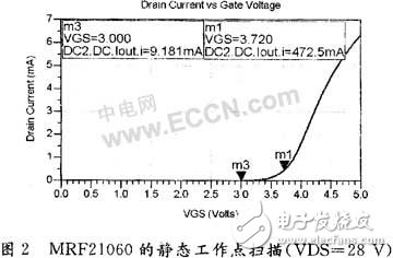
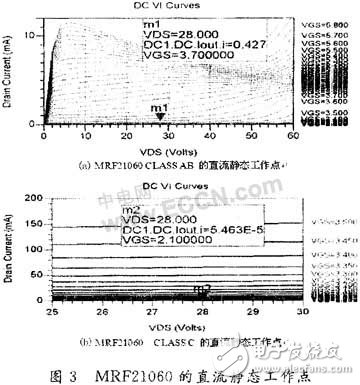
According to Doherty design principles, the main amplifier should be saturated when the auxiliary amplifier starts to activate, ensuring optimal efficiency. For the MRF21060, the static operating point for class AB is around 3.7 V, while for class C, it is set at 2.1 V. The corresponding quiescent current and voltage values for both bias states are illustrated in Figure 3.
#### 1.2.2 Circuit Matching Design
After selecting the appropriate components and setting the bias points, the next step is to design the matching network. Impedance matching is essential to ensure that the main and auxiliary amplifiers operate efficiently and in phase. Additionally, a 90° combiner is designed to combine the outputs of the two amplifiers, ensuring that the final signal is coherent and powerful enough for the intended application.
The DMX console is the central controller for controlling all stage lights and special effects equipment. Almost all equipment needs to be connected to it, and users use it to issue control commands to all equipment. It can be controlled in real time, or the device can be programmed to display specific effects at a fixed time. Even with the stage equipment, the DMX console is also essential, just like there are more soldiers, the commander still needs to give orders to them. There are also many different types controllers to work for different quantity Stage Lights.

DMX Controller, DMX Consule
Guangzhou Cheng Wen Photoelectric Technology Co., Ltd. , https://www.cwdisplay.com