The RF power amplifier is a crucial component in wireless communication systems, especially in base stations where it accounts for approximately one-third of the total cost. Ensuring the linearization of power amplifiers at a low cost is essential for improving system performance and reducing operational expenses. High-efficiency and high-linearity power amplifiers have become a focal point of research, particularly in the context of WCDMA technology. In China, only a limited number of companies are capable of producing WCDMA power amplifiers exceeding 10 W due to the stringent linearity requirements. Most standard back-off methods result in outputs of just a few watts, which are insufficient for base station applications and are typically used in small-scale repeaters instead.
The key challenges in power amplifier design lie in achieving both high linearity and efficiency. The feedforward architecture is a well-established technique for improving linearity, while digital predistortion (DPD) is increasingly seen as the future direction in industry. As communication systems evolve, efficiency has gained more attention, with the Doherty amplifier structure emerging as a promising solution. Combining feedforward techniques with Doherty structures or integrating Doherty with DPD can significantly enhance performance, making such hybrid designs highly valuable in modern systems.
### 1. Doherty Power Amplifier Design
#### 1.1 Overview of Doherty Power Amplifier Principle
The Doherty amplifier consists of two power amplifiers: a main amplifier and an auxiliary amplifier. The main amplifier typically operates in Class B or AB, while the auxiliary amplifier works in Class C. Unlike traditional configurations, the main amplifier is always active, while the auxiliary amplifier engages only during peak signal levels, hence its name "peak amplifier." A 90° quarter-wavelength transmission line is placed behind the main amplifier to perform impedance transformation. This helps reduce the apparent load seen by the main amplifier when the auxiliary amplifier is active, allowing it to deliver higher current. A 90° phase shifter is also added before the auxiliary amplifier to ensure that both outputs are in phase. As shown in Figure 1.
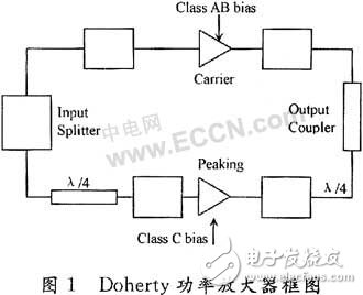
When the input signal is small, only the main amplifier is active. At lower power levels, the main amplifier operates efficiently, reaching up to 78.5% theoretical efficiency. When the signal reaches the saturation point, the auxiliary amplifier turns on, operating in Class C. This introduces a negative impedance effect, effectively lowering the load seen by the main amplifier. As a result, the main amplifier can continue to increase output power even when it is saturated. The combined operation of the two amplifiers leads to higher overall efficiency, with the system achieving 78.5% efficiency at half the peak power level—far better than a single Class B amplifier.
#### 1.2 Doherty Power Amplifier Design
For a 30 W output power, a gain of 50 dB, and an operating frequency range of 2110–2170 MHz, designing a Doherty amplifier requires careful selection of components and circuit configuration.
The first step is to choose appropriate power amplifiers. LDMOS transistors from Motorola are widely used in RF power amplifiers, accounting for over 70% of the market. They are ideal for applications like CDMA, WCDMA, TETRA, and digital TV, where high linearity and wide frequency coverage are required. Since the total gain needed is 50 dB, a multi-stage amplifier configuration is necessary.
To achieve optimal performance, two Motorola MRF21060 transistors are selected. These devices can deliver 120 W at maximum power, and at a 6 dB back-off, they provide the required 30 W output. One transistor is biased to operate in Class AB, while the other is set to Class C. The static operating points are carefully chosen to ensure that the main amplifier saturates when the auxiliary amplifier begins to activate, maximizing efficiency.
A static operating point scan was performed on the MRF21060, and suitable bias settings were identified, as shown in Figure 2.
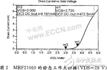
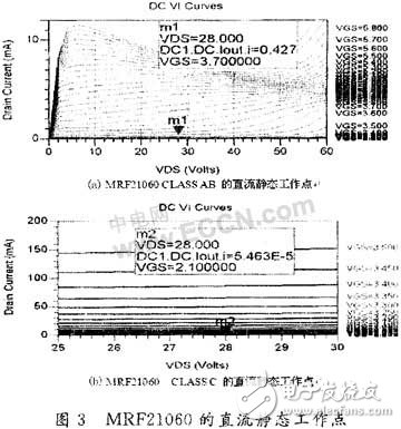
When operating in Class AB, the MRF21060 is biased around 3.7 V, while in Class C, it is biased at 2.1 V. The quiescent current and voltage for these bias conditions are illustrated in Figure 3.
#### 1.2.2 Circuit Matching Design
After selecting the power amplifiers and setting their bias points, the next step is to design the impedance matching network. This ensures that the main and auxiliary amplifiers are properly matched to the load, maximizing power transfer and minimizing signal loss. Additionally, a 90° combiner is designed to combine the outputs of the two amplifiers in phase, ensuring coherent signal synthesis. Proper matching is critical to maintaining the efficiency and linearity of the Doherty amplifier across the desired frequency range.
Outdoor Rental Stage Event LED Display
This series is a professional outdoor waterproof rental LED display, IP65 waterproof level is not afraid of wind and rain and anti-corrosion function. It is used for professional large-scale concerts,
concert stages, various party activities, evening parties, band
performances, etc. Good quality guarant with 2 year warranty,
professional good after-sale service.
As Professional Manufacturer of LED Screen, we fouce on quality and provide very good price and warranty service.
Outdoor Rental Stage Event LED Display,perfect well fit product for your indoor events solution, welcome to consult. Contact us to know more now!

Outdoor Rental Stage Event Led Display,Outdoor Concert Stage Background Wall,Outdoor Stage Rental Led Screen,Events Venue Led Screen System
Guangzhou Cheng Wen Photoelectric Technology Co., Ltd. , https://www.cwdisplay.com