We have briefly introduced the thermal transient test method for LED junction temperature. This method uses the heat sensitive parameter of the LED itself, the voltage change, to calculate the temperature rise to obtain the junction temperature under working conditions. So, in addition to the method of testing, is there any other way to know the junction temperature when the device is working? Industry veterans must know that the junction temperature can actually be calculated!
However, before calculating, we must know the thermal resistance of the device (the thermal resistance of the general device specification), and then use the thermocouple to measure the pin temperature or the case temperature to calculate the junction temperature. So what is the thermal resistance? How does the junction temperature calculate using the thermal resistance and the shell temperature? Here are some explanations for everyone.
First, what is thermal resistance?
First of all, in order to make it easier for everyone to understand, we can borrow the concept of electricity. The concept of thermal resistance is derived from the concept of analog resistance. The similarity between the two is very high. Resistance refers to the physical quantity that hinders current conduction. Correspondingly, thermal resistance is the physical quantity that hinders heat flow conduction. Under the same conditions, the greater the thermal resistance, the less easily the heat flow passes.
If a heat source is connected to several heat conduction paths with unequal thermal resistance values, the heat flow size distribution is the same as the current when the current flows through different resistors, as shown in Figure 1.
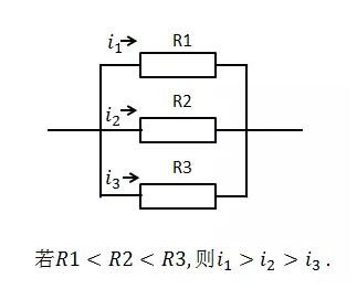
Current (heat flow) profile
That is to say, if there are several heat conduction paths between two isothermal points, one of which has a very large thermal resistance value and the other has a very small thermal resistance value, the heat is almost always from the thermal resistance value. The small path passes, which is the theoretical basis that will be quoted below.
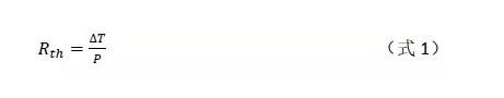
Next, let's look at the physical definition of thermal resistance. The so-called definition is to tell us how to calculate the thermal resistance value. As mentioned above, the definition of thermal resistance can be analogized to resistance. The resistance is the ratio of the voltage difference ΔU across the conductor to the current I through the conductor. Then we can easily understand the definition of thermal resistance. The thermal resistance is defined as the ratio of the temperature difference ΔT across the material on the heat flow path to the thermal power P flowing through the channel. Formula expression is
After warming up, please go into the JESD51-1 standard to see the thermal resistance of the semiconductor device.
1.1 Thermal resistance structure
The thermal resistance of semiconductor devices is defined in detail in the JESD51-1 standard.
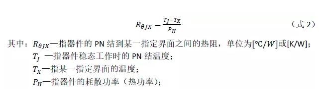
We can see that (Equation 2) is actually a complementary form of (Equation 1), and it is quite intuitive and convenient to analyze the structure of a semiconductor device such as an LED by (Equation 2).

LED package structure sectional view
Taking the package structure of the common LED in Fig. 2 as an example, it is assumed that the heat generated by the heat source is conducted from the PN junction all the way down, passing through the chip-solid crystal layer-device holder-thermal paste-heat sink, and the heat sink and the ambient temperature are considered to be thermally balanced. So how do you know the exact thermal resistance of the PN junction to the bottom of the device holder? Let us introduce a new analysis method - structure function method.
1.2 structure function
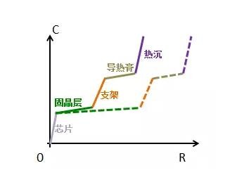
We refer to a function that can describe the thermal resistance heat capacity structure of the material inside the semiconductor device as a structure function. In the structure function, the thermal resistance heat capacity characteristics of each material can be expressed intuitively, as shown in Figure 3. As the ladder, from left to right, the chip, the solid crystal layer, the support, the thermal paste, the heat sink .

Device structure and structure function
Mentioned here, by the way, readers will review again. In the previous article, we mentioned that whether it is a diode, a triode, a FET or an IGBT, the junction temperature and thermal resistance of these semiconductor devices can be measured by T3ster. Moreover, after the mathematical operation, the thermal resistance of each layer structure on the heat conduction path can be analyzed to find the heat dissipation bottleneck. What is said here is actually the power of the structure function. If there is a problem with the material of one of the layers inside the device (such as the solid crystal layer), it can be clearly expressed in the structure function function, as shown in Figure 4.
The difference between the solid crystal anomaly in the structure function (the solid line is the solid crystal normal sample, and the broken line is the solid crystal abnormal sample)
The abnormality of the solid crystal is manifested by the increase of the thermal resistance of the solid crystal layer, so that the structure under the solid crystal is translated to the right side of the normal sample curve. Through the structure function, we don't need to destroy the sample to give out the abnormalities that are invisible to the inside of the device, just like X-ray! With the structure function, whether you want to know which interface to which interface thermal resistance, we can divide it layer by layer, the aforementioned mentioned the thermal resistance value of the PN junction to the bottom of the device holder is Nothing to say.
Well, we get the thermal resistance (called) from the PN junction we want to know to the bottom of the device holder through the structure function. The thermal resistance of the device given in the specifications of the general device is strictly this. Now let's answer the question mentioned at the beginning of the text: How to use this thermal resistance value to calculate the junction temperature.
Miniature Slip Ring,Slip Ring Parts,Slip Ring Type Induction Motor,Slip Ring Rotor
Dongguan Oubaibo Technology Co., Ltd. , https://www.sliprob.com