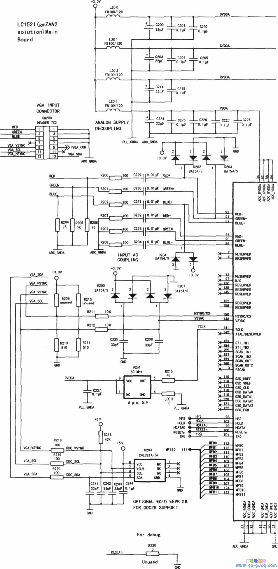
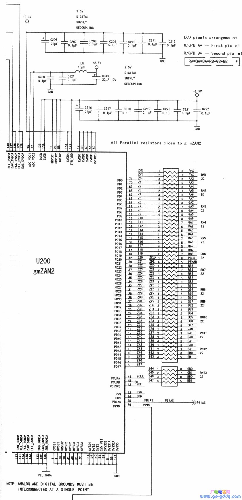
gmZAN2 is a high-performance, ultra-large-scale integrated circuit designed for digital image processing. It is primarily used in the Konka LC-1521T liquid crystal color television. As shown in the diagram, this chip has various functions assigned to its pins, including power supply connections, signal outputs, and control inputs.
Pin 1, 8, 18, 30, 41, 49, 61, 72, 114, 126, 140, 151, 158, 5, 59, and 147 are all ground connections.
Pin 2 is a reserved terminal, not used.
Pin 3 (PSCAN) is also unused.
Pin 4 is another reserved pin, not used.
Pin 6 (PD47) is a display port, but it is currently unused.
Pin 7 (PD46) is another display port, also not in use.
Pin 9 (PD45) is connected to the RB1 output and sends signals to RN12.
Pin 10 (PD44) is the RBO output, also directed to RN12.
Pins 11, 21, 58, 125, 139, and 149 are connected to the +2.5V power supply.
Pins 12, 33, 40, 65, 60, and 108 are connected to the +3.3V power supply.
Pin 13 (PD43) is the BA1 output, sent to RN12.
Pin 14 (PD42) is the BAO output, also sent to RN12.
Pin 15 (PD41) is the RGA1 output, connected to RN11.
Pin 16 (PD40) is the GAO output, sent to RN11.
Pin 17 (PD39) is the RA1 output, connected to RN11.
Pin 19 (PD38) is the RAO output, also sent to RN11.
Pin 20 (PD37) is the BB7 output, directed to RN10.
Pin 22 (PD36) is the BB6 output, sent to RN10.
Pin 23 (PD35) is the BB5 output, connected to RN10.
Pin 24 (PD34) is the BB4 output, sent to RN10.
Pin 25 (PD33) is the BB3 output, connected to RN9.
Pin 26 (PD32) is the BB2 output, sent to RN9.
gmZAN2 Image Digital Processing Control Circuit (a)
Pin 27 (PD31) is the GB7 output, sent to RN9.
Pin 28 (PD30) is the GB6 output, directed to RN9.
Pin 29 (PD29) is the GB5 output, sent to RN8.
Pin 31 (PD28) is the GB4 output, connected to RN8.
Pin 32 (PD27) is the GB3 output, sent to RN8.
Pin 24 (PD26) is the GB2 output, directed to RN7.
Pin 35 (PD25) is the RB7 output, connected to RN7.
Pin 36 (PD24) is the RB6 output, sent to RN7.
Pin 37 (PD23) is the RB5 output, directed to RN7.
Pin 38 (PD22) is the RB4 output, sent to RN7.
Pin 39 (PD21) is the PENAB control signal output.
Pin 42 (PD20) is the PCLK clock signal output.
Pin 43 (PDISPE) is for ZDE control.
Pin 44 (PCLKA) is for ZCLK control.
Pin 45 (PCLKB) is unused.
Pin 46 (PD19) is the RB3 output, sent to RN6.
Pin 47 (PD18) is the RB2 output, connected to RN6.
Pin 48 (PD17) is the BA7 output, sent to RN5.
Pin 50 (PD16) is the BA6 output, directed to RN5.
gmZAN2 Image Digital Processing Control Circuit (b)
Pin 54 (PD12) is the BA2 output, sent to RN4.
Pin 55 (PD11) is the GA7 output, connected to RN4.
Pin 56 (PD10) is the GA6 output, sent to RN4.
Pin 57 (PD9) is the GA5 output, directed to RN3.
Pin 62 (PD8) is the GA4 output, connected to RN3.
Pin 63 (PD7) is the GA3 output, sent to RN3.
Pin 64 (PD6) is the GA2 output, directed to RN3.
Pin 66 (PD5) is the RA7 output, connected to RN2.
Pin 67 (PD4) is the RA6 output, sent to RN2.
Pin 68 (PD3) is the RA5 output, directed to RN2.
Pin 69 (PD2) is the RA4 output, sent to CN202 as shown below.
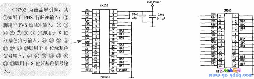
CN202/CN203 LCD Pin Circuit
Pin 70 (PD1) is the RA3 output, connected to RNI.
Pin 71 (PDO) is the RA2 output, sent to RN1.
Pin 73 (PVS) is for ZVS input (field pulse).
Pin 74 (PHS) is for ZHS input (line pulse).
Pin 75 (PBIAS) is for PBIAS control.
Pin 76 (PPWR) is for PPWR (standby) control.
Pins 77 and 79 are connected to +2.5V power supply.
Pins 78 and 80 are grounded for analog and digital circuits.
Pins 81, 82, 85, 89, and 93 are grounded.
Pins 84, 88, 92, and 96 are connected to +3.3V power supply, controlled by U202 as shown in Figure 1-20.
Pin 83 is a reserved pin, not used.
Pin 86 is the BLUE- input for blue base color negative.
Pin 90 is the GREEN- input for green base color negative.
Pin 91 is the GREEN+ input for green positive phase.
Pin 94 is the RED- input for red base color negative.
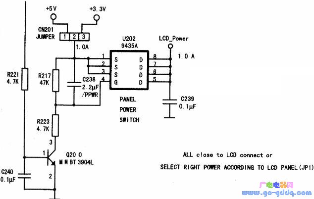
U202/(9135A) Power Control Circuit
Pin 95 is the RED+ input for red positive phase.
Pin 97 is N/C, not used.
Pin 98 is HFS, line pulse input.
Pin 99 (HDATA) is data bus input/output.
Pin 100 (RESETn) is reset signal.
Pin 101 (IRQ) is remote control signal input.
Pin 102 (MFB9) is HDATA3 input/output.
Pin 103 (HCLK) is clock signal input.
Pin 104 (MFB8) is HDATA2 input/output.
Pin 105 (MFB7) is HDATA1 input/output.
Pin 106 (MFB6) is an external 10kΩ resistor to ground.
Pin 107 (MFB5) is another external 10kΩ resistor to ground.
Pin 109 (MFB4) is for RIGHT control.
Pin 110 (MFB3) is for SELECT control.
Pin 111 (MFB2) is for PWR-SW control.
Pin 112 (MFBl) is for MENU selection.
Pin 113 (MFBO) is for LEFT control.
Pin 115 (OSD_HREF) is not used.
Pin 116 (OSD_VREF) is not used.
Pin 117 (OSD_CLK) is unused.
Pin 118 (OSD_DATAO) is not used.
Pin 119 (OSD_DATAl) is unused.
Pin 120 (OSD_DATA2) is not used.
Pin 121 (OSD_DATA3) is not used.
Pin 122 (OSD_FSW) is not used.
Pin 123 (MFB11) is for LEDORANGE control.
Pin 124 (MFB10) is for LED-GRN-EN control.
Pins 127, 131, 134, 138, 144, 133, 132, and 146 are grounded.
Pin 130 is a reserved pin, not used.
Pin 135 is also a reserved pin, not used.
Pin 141 (TCLK) is a 50MHz clock signal input.
Pin 142 (XTAL/RESERVED) is not used.
Pin 145 is a reserved pin, not used.
Pin 148 (VSYNC) is the field sync pulse input.
Pin 150 (HSYNC/CS) is the line sync pulse input / chip select pulse input.
Pin 152 is a reserved pin, not used.
Pin 153 (STl-TMl) is not used.
Pin 154 (STl-TM2) is unused.
Pin 155 (SCAN.INl) is not used.
Pin 157 (SCAN-IN2) is not used.
Pin 159 (SCAN-OUTl) is not used.
Pin 160 (SCAN-OUT2) is not used.
"Cooling Film" typically refers to a type of material designed to reduce heat buildup, often used in electronic devices, buildings, or vehicles. These films can work through various mechanisms such as reflecting sunlight, dissipating heat more efficiently, or insulating against external heat sources. They can be made from different materials and are applied in various ways depending on their intended use.
For example:
- **Electronic Cooling Films:** These are often used in smartphones, laptops, and other electronic devices to help manage heat generated by internal components. They might be applied directly to the surface of a device or integrated into heat sinks.
- **Building Cooling Films:** Applied to windows or exterior surfaces, these films can reflect a portion of the sun’s heat away from the building, helping to keep interiors cooler.
- **Automotive Cooling Films:** Used in car windows or on the vehicle's body to reduce the amount of heat entering the cabin.
If you have a specific application or context in mind for "Cooling Film," please provide more details so I can offer more targeted information!
self-cleaning radiative,Energy saving,cooling film,radiative cooling,ultra-high solar reflectivity,Car window cooling film
ZHONG HAN INTERNATIONAL TRADE CO., LTD , https://www.cck-ht.com