Building a high-performance FM/AM radio using the TA2111F is straightforward and efficient. One of the key advantages of this IC is its built-in AFC circuit, which eliminates the need for an external varactor. All you need is a single 5pF capacitor. Additionally, the FM IF section uses a ceramic filter instead of traditional intermediate frequency transformers, making the design more stable and easier to assemble. The stereo decoding process also doesn't require tuning the 19kHz pilot signal, further simplifying the setup.
The author tested a homemade FM stereo radio using the TA8127N and found that the TA2111F-based unit outperformed it in several ways. It captured more stations, had less noise, and provided better stereo light performance. The TA2111F comes in a flat package, while the TA2111N is available in a dual in-line package, offering different options depending on your build preference.
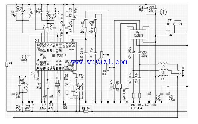
Figure 1 shows the circuit diagram of the radio, while Figures 2 and 3 are the printed circuit board layouts. Since this unit does not support AM band operation, pins {7}, {20}, and {24} of the IC are not used. Pin {16} is the band switching pin, and shorting C6 allows switching to the AM band. Shorting C8 changes the FM stereo mode to mono.
The device uses the lead from a stereo headphone as the antenna. The FM signal is input through pin {1} of the TA2111F via a bandpass filter made up of L4, C19, C18, and C16. By following the pin configuration of the TA2111F, you can trace the signal flow. Pins {13} and {14} output the signal, which is then amplified by the low-power bi-amplifier TDA2822 to drive the stereo headphones.
Component selection is crucial for optimal performance. A 4-section variable capacitor is used, with the two-section capacitance set between 4 and 24 pF for FM. L1 is wound with 3.5 turns on a 5mm round bar using 1mm enameled wire. L2 is wound with 3.5 turns on a 4mm bar using 0.7mm enameled wire. After mounting L1 and L2 on the board, a small sponge is inserted into the coil, and melted paraffin is added to dampen vibrations. L4 is wound on a 4.5mm bar with 5 turns of 0.7mm enameled wire. L3 serves as the FM frequency discrimination coil. A miniature dual-gang potentiometer is used for tuning.
Debugging after assembly is essential. Once powered on, adjust the volume and rotate the variable capacitor. If you can pick up several stations, the build is likely correct. Follow these steps for fine-tuning:
- Adjust the receiving range (88–108MHz): Start by turning the variable capacitor clockwise to the bottom. Use a screwdriver to adjust the oscillator's fine-tuning capacitor until the radio picks up a station around 108MHz. Then turn the capacitor back to the bottom and use a toothpick to adjust the spacing of L2’s windings to receive a station near 88MHz. Repeat this process until the radio can reliably pick up stations at both ends of the FM band.
- Improve low-end sensitivity: Set the variable capacitor near 106MHz and adjust the antenna’s fine-tuning capacitor with a screwdriver until the speaker noise is maximized. Then move the capacitor to around 92MHz and adjust the spacing of L1’s windings with a toothpick, again maximizing the noise level. Repeat this several times for best results.
- Frequency adjustment: Use a screwdriver to adjust the magnetic core of L3 to minimize any noise or interference in the speaker.
With careful assembly and proper tuning, the TA2111F-based FM radio can deliver excellent performance, making it a great choice for DIY enthusiasts looking for a simple yet powerful solution.
Refurbished Gaming Laptops,Refurbished Laptops Under $100,Used Gaming Laptops For Sale,Second Hand Gaming Laptop
Guangzhou Panda Electronic Technology Co., LTD , https://www.panda-3c.com