Higher system efficiency and power density are the primary goals of today's data and telecom power system design. To achieve this goal, semiconductor developers have developed a new generation of trench MOSFETs with gate-shielded structures that significantly reduce power losses at full load and light load.
How to achieve higher system efficiency and power density is the core of modern data and telecom power systems, because a small and efficient power system can save space and energy costs. From the perspective of topology, the transformer converts AC power into synchronous rectification of DC power, which is the main module architecture of the secondary side of the switching power supply in many applications, which can improve the conduction loss and switching loss in energy conversion. From a component point of view, power metal oxide semiconductor field effect transistors (MOSFETs) have made great strides over the past decade, resulting in new topologies and high power density power supplies. The main requirements for synchronous rectification MOSFETs are as follows:
. Low trench on-state resistance RDS(ON)
. Low gate charge QG
. Low reverse recovery charge QRR and common source output capacitor COSS
. Less active body diode characteristics
. Low gate leakage Qgd / gate charge Qgs ratio
Package mode affects MOS power consumption
Currently, semiconductor manufacturers use Shielded Gate technology to design high-power MOSFETs such as PowerTrench MOSFETs from Fast Semiconductor. This article uses the PowerTrench MOSFET as an example to analyze the power loss of the servo power supply or the power loss of the telecom rectifier.
. Conduction loss
If the on-resistance and the drain current of the MOSFET product are lower than the forward voltage drop of the diode, the power loss of the synchronous rectification will be lower. Therefore, synchronous rectification on the secondary side is an excellent solution to improve system efficiency. The conduction loss can be calculated by the following formula 1:
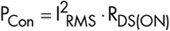 Formula 1
Utilizing the current mainstream voltage MOSFET technology, the TO-220 standard package can be reduced to 1?2 milliohms (mohm) according to the rated voltage, while the package resistance of high voltage MOSFETs has not yet received attention. . Unlike high-voltage MOSFETs, the package of a medium-voltage MOSFET itself also accounts for a portion of the total impedance due to factors such as bonding, lead, and source mental. Through the SMD package such as Power56, the total on-resistance of the medium-voltage MOSFET can be significantly reduced, and the package inductance can be reduced to reduce the voltage surge.
. Gate drive loss
The gate driver drive loss is closely related to the gate charge QG. In low-voltage applications, the drive loss can account for the majority of the total power loss because the voltage switch has only very low conduction losses compared to high-voltage switches. In the case of light loads, the conduction loss is minimal, so the drive loss is more important. It is well known that the drive loss can be calculated by the following formula 2:
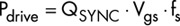 Formula 2
In synchronous rectification, current flows from the source of the MOSFET to the drain during turn-on and through the body diode during dead time (Dead TIme). Since the MOSFET is a soft switch, dVds/dt is zero at the turn-on and turn-off of the switch, so the gate-source voltage of the power MOSFET does not have a plateau during synchronous rectification. Therefore, the gate charge generated between SR and QSYNC is approximately equal to the gate-drain QGD of the gate charge minus the total gate charge QG. As shown in Table 1, the QSYNC of the latest gate-shielded trench MOSFET can be reduced by 28% and 34%, respectively, compared to the conventional trench gate MOSFET and the 75V/3.3m control element. Figure 1 shows the loss ratios of the drive loss and conduction loss of the above three components. The test environment is a 12 volt (V) synchronous rectification platform with a gate drive voltage of 10V and a switching frequency of 100kHz. Two of the synchronous switches have a gate drive loss that is more than three times the conduction loss at 10% output load. As can be seen from Figure 1, the gate-shielded MOSFET can greatly reduce the drive loss due to small QSYNC under light load conditions.
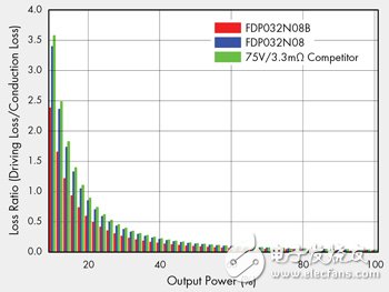
Figure 1 Comparison of loss ratios based on output load
. Body diode loss
During the dead time, the body diode is conducting. When the body diode is turned on, it generates considerable power loss because the voltage drop caused by the PN junction is higher than that of the MOSFET channel. The power loss caused by the conduction of the body diode during the dead time can significantly reduce the overall efficiency. Especially at low voltage and high frequency, the conduction loss can be known by Equation 3:
![]() Formula 3
Formula 3
At the moment the MOSFET is turned off, the reverse recovery charge Qrr will disappear, and the common source output capacitor COSS will be charged until the conversion voltage of the secondary side is satisfied. The diode reverse recovery charge Qrr also causes power loss when the switch is turned off. The power loss due to the characteristics of the body diode can be known from Equation 4:
![]() Formula 4
Formula 4
The charge QOSS stored in the output capacitor also causes power loss and is proportional to the switching frequency and VDS. The power loss due to COSS can be found by Equation 5:
![]() Formula 5
Formula 5
1, Smart app syncs with fitness apps. You can use the scale even without your phone nearby. The data will sync to the app once it is connected again.
2, 13 Body Composition Analysis. Uses Bioelectric Impedance Analysis technology to track Weight, BMI, Body Fat Percentage, Body Water, Skeletal Muscle, Fat Body Weight, Muscle Mass, Bone Mass, Protein, Basal Metabolism, Visceral Fat, Subcutaneous Fat and Body Age. Considering body composition, it can give you an overview of the indicators percentages and allow you to set easy weight and fat goals.
3, Rechargeable Internal Battery. USB rechargeable function with a built-in lithium battery, no need disposable batteries. A long-lasting and durable battery can be used for a long time.
4, Unlimited Users. One scale for whole family use. Allowing you to track information, record, store profile and make a chart to visualize your trend.
5, High precision sensors measure in increments of 0.2 lb with 396lbs capacity. 4 sensitive electrodes, 6mm tempered glass platform
Bluetooth Scale,Body Weight Scale,Bluetooth Body Fat Scale,Bluetooth Bathroom Scale
Axiswell Technology Co., Ltd , https://www.medhealthycare.com