Next-generation base station transmitters and receivers not only employ a single-radio multi-carrier (MC) technology, but also introduce multiple modes in a single transmitter path, which imposes broader requirements on bandwidth. For example, GSM, W-CDMA, and LTE multi-carriers can be simultaneously transmitted from a multi-standard radio (MSR) base unit. Cellular networks can support multiple formats, which is important to reduce base station size and cost. In view of this, the MSR base station will smoothly and steadily transition from the currently deployed 2/3G wireless system to 3.9G (eg LTE) or even 4G (eg LTE-Advanced) technology. This is good news for network operators, service providers and consumers. However, using the MSR multi-carrier configuration makes testing the MSR base station transmitter more challenging. To ensure the smooth deployment of MSR base stations, it is necessary to address measurement challenges in a fast and efficient manner.
New requirements
When the base station supports multiple radio access technologies, the 3GPP Release 9 standard contains a series of documents related to the MSR (3GPP TS37 Release 9) and requirements for base station conformance testing. These documents cover MSRs using 3GPP Frequency Division Multiplexing (FDD) standards such as LTE FDD, W-CDMA/HSPA and GSM/EDGE, and 3GPP Time Division Multiplexing (TDD) standards such as LTE TDD and TD-SCDMA. Carrier combination. The receiver conformance test is similar to each single-mode test, and the transmitter conformance test must be performed under the MSR multi-carrier allocation scenario.
When testing MSR multi-carrier configurations, the RF requirements defined by the TS37 document specify channel power measurements, error vector quality (EVM), frequency error (calculation is the same as EVM), spurious emissions, residual radiation in the operating band, or spectrum. Radiation template (SEM). When testing each carrier of each system, it is required to measure the ACLR, the occupied bandwidth (OBW), and the time synchronization between the transmitter paths. Although there are no mandatory requirements for the above three measurements in the MSR multi-carrier configuration, some base station manufacturers still want to test. This kind of test needs to be close to the actual application scenario, covering all the standards supported by the base station under test, and can provide users with excellent test efficiency.
Performing spectrum measurements
MSR spectrum measurements are very similar to single-mode tests and can be done by scanning analysis with a signal analyzer or spectrum analyzer (SA) or by fast Fourier transform (FFT) analysis of a vector signal analyzer. Scan analysis is more suitable for out-of-band or out-of-band measurements (such as spurious emissions, ACLR, and SEM) because the bandwidth setting needs to be larger than the bandwidth used for single-carrier measurements.
Figure 1 shows a scanned spectrum view of carrier channel power measured in accordance with the MSR conformance test defined by 3GPP TS37.141. In this example, the measurement application for the MSR scans the MSR channel power measurement based on the spectrum analyzer, making measurement very simple. Alternatively, you can manually configure the spectrum analyzer's resolution bandwidth (for example, 100 kHz) for scanning. The bandwidth needs to be narrow enough to distinguish between GSM carriers and a series of band power cursors for each carrier of interest.
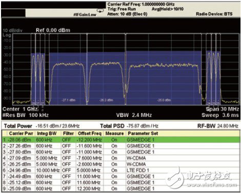
Figure 1. Agilent N9083A MSR measurement application running on an X-Series signal analyzer to perform multi-carrier channel power measurements. The MSR signal under test is an example of 3GPP Test Configuration 4c (TC4c), assuming that the base station transmitter has an RF bandwidth of 25 MHz. It consists of a total of 6 GMSK/8PSK carriers (3 carriers each on the lowest and highest frequency of the RF bandwidth), 2 W-CDMA carriers and 1 LTE FDD 10-MHz carrier.
Digital modulation quality measurement
When evaluating signal modulation quality, such as EVM for each carrier in an MSR multi-carrier configuration, the primary consideration for test engineers is how to collect all available active carriers at once in the wide bandwidth supported by the MSR base station RF port. Keep in mind that this specification does not mandate the simultaneous capture of all active carriers by an analyzer with a wideband acquisition front end.
For transmitter compliance testing, measurements are made using any repeating pattern waveform of the device under test (eg, various test modes). The 3GPP TS37.141 MSR Base Station Conformance Test Standard defines several MSR multi-carrier allocation patterns for test configuration. Therefore, even without the use of broadband front-end hardware to simultaneously capture all available MSR multi-carriers, transmitter conformance testing can be accomplished with traditional signal acquisition methods.
Essentially, the test engineer captures each single carrier and performs modulation quality measurements one by one, then uses the appropriate narrow acquisition input bandwidth front end to capture each single carrier. In the second step, the engineer converts the frequency to the second carrier, captures and measures the EVM, and so on. This approach eliminates the need for expensive broadband front-end hardware to cover all carriers at once, and does not require large waveform sampling to compute EVM after capturing wideband signals, making it an easy-to-use, cost-effective method for engineers. The widest cellular carrier bandwidth currently is the 20-MHz bandwidth of LTE. But what about LTE-Advanced? According to LTE Release 10, LTE-Advanced will support system bandwidths up to 100-MHz. Since LTE-Advanced supports carrier aggregation, each component carrier has a bandwidth of up to 20-MHz. The user needs to spend extra time and effort to convert each carrier measurement one by one, but the time and effort involved will depend entirely on the continuous acquisition and demodulation calculation process/algorithm in the tester/analyzer device or external control program. If you choose "fast local oscillator and inter-carrier mode conversion", its disadvantage in terms of test rate will be very insignificant.
The cost of simultaneous capture of all active carriers of interest using wide bandwidth analyzer hardware is higher than for narrow bandwidth hardware, but it verifies and troubleshoots transient events in MSR wireless devices (eg functional design verification and actual system operation testing) ) Very effective (Figure 2). Each carrier is taken from the acquired wideband waveform and EVM measurements are taken separately. The captured sampling result includes all of the simultaneous active carriers.
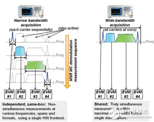
Figure 2. This figure compares the continuous acquisition (left) of each carrier using narrow-bandwidth hardware and simultaneous acquisition (right) of all carriers using wide-bandwidth hardware for modulation analysis.
Regardless of whether a wide bandwidth or narrow bandwidth hardware analyzer approach is used, each carrier of interest is required to be filtered using an appropriate receiver filter. The filter is capable of suppressing adjacent carrier power interference, allowing the analyzer to achieve good synchronization and modulation stability for each carrier under multi-carrier conditions. Taking the W-CDMA (or TD-SCDMA) carrier as an example, the standard specification clearly defines the shape of the receiver filter. The filter is 3.84 MHz (1.28 MHz for TD-SCDMA) and the root raised cosine filter with a roll-off factor of 0.22. . For systems such as GMSK and LTE, there is no such clear specification. Instead, it may be necessary to add an adjacent carrier suppression filter to the analyzer with a large variation in roll-off factor (even if it affects the modulation quality).
to sum up
The spectrum scanning method is still applicable when performing spectrum and power measurements on MSR multi-carrier base station transmitter devices. It can also be used for measurements on each carrier transmitter device. When analyzing the modulation quality of each carrier in the MSR multi-carrier configuration, two methods can be employed. In the first method, each carrier is continuously acquired using a narrow bandwidth hardware front end. This method assumes that the MSR signal under test is an arbitrary repeat test mode signal, which has the advantages of simplicity and low cost. The second method uses a wide bandwidth hardware front end to acquire all carriers simultaneously. This method can truly capture all carriers at the same time in order to troubleshoot transient events, which is costly. The overall test efficiency of each method depends on the design or programming of the test sequence algorithm.
About the Author
Moto Itagaki is a senior application product planner for Agilent Technologies' cellular and wireless signal analysis. He has more than 15 years of experience in wireless technology and was originally a R&D engineer in Agilent's mobile communications test. As a product planner, Itagaki is driving the development of GSM/EDGE, W-CDMA/HSPA, IS95, cdma2000, 1xEV-DO, 802.16-OFDMA, LTE and MSR test applications. Itagaki is based in Kobe, Japan and holds a master's degree in electronics and communications engineering from Tohoku University, Japan.
Our company Ningbo Beilun Tiaoyue Machine Co., Ltd. can make kinds of spools according to customer's drawing or samples,such as Steel Reel,Steel Wire Reel,Steel Drum.
When you need the strength and durability of a steel reel, ONEREEL has the product for you.
Whether you need a tubular reel for lightweight shipping of pipe or conduit, a custom-designed process reel for take-up and take-off solutions in heavy-duty processing industries or a corrugated steel reusable design for wire and cable applications, our line of steel reels is tailored to satisfy your unique needs.
For customer service, call 0086-13777009159(mobile) or 0086-574-26889982(telephone)

Steel Wire Spool, Steel Cable Reel, Steel Bobbin, Steel Cable Spool, Wire Spool, Cable Reel,Steel Reel,Steel Wire Reel,Steel Drum
NINGBO BEILUN TIAOYUE MACHINE CO., LTD. , https://www.spool-manufacturer.com