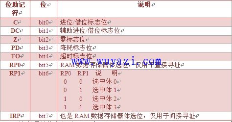
1. Status register STATUS
2. Indirect addressing registers INDF and FSR
3. Registers PCL and PCLATH related to the program counter PC
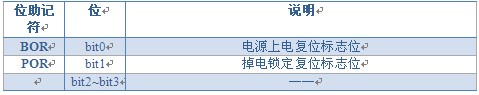
4. Power Control Register PCON
PIC Microcontroller Instruction System
The PIC16F87X has a total of 35 instructions, each being a 14-bit single-byte instruction. These instructions are categorized into three groups: byte-oriented operations (17), bit-oriented operations (4), and constant and control operations (14).
PIC Configuration Word Settings
I’ve learned two methods to configure the PIC configuration word so far:
1. Using "__CONFIG" followed by the value after setting the configuration word.
2. Using "__CONFIG" with bits and status of each configuration word. The format is as follows:
;========================================================== =================
; Configuration Word Definition
;========================================================== =================
__CONFIG _DEBUG_OFF&_CP_ALL&_CPD_ON&_LVP_OFF&_BODEN_OFF&_PWRTE_ON&_WDT_OFF&_HS_OSC ; Configuration Word Definition
Indirect Addressing, INDF and FSR Registers
The INDF register is not a physical register; accessing it results in indirect addressing. Instructions targeting the INDF register actually access the registers pointed to by the FSR register. Reading from INDF itself returns 00H. Writing to INDF through indirect addressing results in a dummy operation (though it may affect status bits). A valid 9-bit address is formed by combining the 8-bit FSR register with the IRP bit (from STATUS).
Example of Indirect Addressing:
Example: Write values 30H to 7FH into memory locations 30H to 7FH sequentially. COUNT is the count register.
;========================================================== ================
; Continuous address write data subroutine (indirect addressing)
;========================================================== ================
WR_ADS: MOVLW 30H ; Initialize RAM content
MOVWF FSR ; Start from 30H
MOVLW 30H ; Assign 30H to 30H
MOVWF COUNT ;
INTRAM: MOVF COUNT, 0 ; Assign 30H to 7FH
MOVWF INDF ; Access INDF
INCF COUNT, 1 ; Increment COUNT
INCF FSR, 1 ; Move pointer
BTFSS COUNT, 7 ; Check if COUNT is 1 (COUNT=0 at 7FH)
GOTO INTRAM ; Loop
RETURN ; Return from subroutine
Register Definition in PIC Microcontroller Programming
In PIC microcontroller programming, you need to define the registers used in your program. This is usually done using pseudo-instructions. However, a more efficient method is to use the "CBLOCK" directive followed by the address of the register. You can define multiple registers at once, and their addresses will be automatically assigned. Use "ENDC" to finish the definition.
Example:
;========================================================== ================
; Space definition
;========================================================== ================
CBLOCK 20H ; Define starting from 20H
COUNT ; Address is 20H
W_TEMP ; Address is 21H
STATUS_W ; Address is 22H
ENDC ; End of definition
IO Port Operations in PIC Microcontroller
Setting a bit in the TRISX register sets the corresponding output driver to high-impedance mode. Clearing a bit in TRISX latches the output latch to the specified pin.
RCSTA Register Operation Notes
During data reception, if the received data is read in time, the USART will normally receive the next data. However, if an interrupt occurs during reception or another operation is interrupted, the RCREG data may be delayed. In this case, the shift register will no longer load new data into RCREG. As a result, even if data is transmitted, RCIF will not be set, and the reception is interrupted. If no action is taken, communication will fail.
The cause is that the interruption delays reading the data, triggering the overflow error flag OERR (in RCSTA). This flag disables the shift register from placing received data into RCREG and stops further reception.
Solution: Clear the OERR flag. To do this, you must clear the CREN bit (RCSTA) first, then re-enable it. Otherwise, only one byte can be received.
HA series hood is suitable to small heavy duty connectors, it is widely used in machinery, wind energy, rail transportation, power systems, photovoltaic industry, communications industry, engineering equipment and other fields. Heavy Duty Connector is designed for modular production pre-wiring and satisfying severe environmental conditions, applied in rail transit,industrial automation and equipment manufacturing fields. Compared with traditional wiring methods,use of heavy duty connector can reduce site wiring operation after equipment or vehicle leaves the workshop,enhance production efficiency and reduce quality risk of site wiring.
Ha Series Connector,4-Pin Heavy Duty Connector,3 Pin Heavy Duty Connector,Industrial Heavy Duty
Kunshan SVL Electric Co.,Ltd , https://www.svlelectric.com