Electromagnetic interference EMI The interference signals generated by electronic equipment are transmitted through wires or common power lines, and mutual interference is called conducted interference. Conducted interference has caused confusion for many electronic engineers. How to solve conducted interference? Find the right method, you will find that the conducted interference is very easy to solve, as long as the number of EMC filters in the power input circuit is increased, and the parameters of each filter are properly adjusted, basically meet the requirements, the seventh circuit protection The organizers of the Electromagnetic Compatibility Symposium summarized eight major countermeasures to solve the problem of dealing with conducted interference.
Countermeasure 1: Minimize the effective area of ​​each loop

figure 1
Conducted interference is divided into differential mode interference DI and common mode interference CI. Let's first look at how conducted interference is generated. As shown in Figure 1, the loop current produces conducted interference. There are several loop currents in it. We can think of each loop as an induction coil, or the primary and secondary of the transformer coil. When there is current flowing in one loop, the induced electromotive force will be generated in the other loop. , causing interference. The most effective way to reduce interference is to minimize the effective area of ​​each loop.
Countermeasure 2: Shielding and reducing the area of ​​each current loop and the area and length of the live conductor

As shown in Fig. 2, e1, e2, e3, and e4 are differential mode interference signals generated by the magnetic field to the loop; e5, e6, e7, and e8 are common mode interference signals induced by the magnetic field to the ground loop. One end of the common mode signal is the entire circuit board, and the other end is the earth. The common end of the circuit board cannot be counted as ground. Do not connect the common end to the outer casing. Unless the casing is connected to the ground, the common end and the outer casing will increase the effective area of ​​the radiating antenna, and the common mode radiation interference will be more serious. . One way to reduce radiated interference is to shield, the other is to reduce the area of ​​each current loop (magnetic field interference), and the area and length of the live conductor (electric field interference).
Countermeasure 3: Magnetically shield the transformer and minimize the effective area of ​​each current loop

As shown in Figure 3, among all electromagnetic induction disturbances, the interference caused by the leakage inductance of the transformer is the most serious. If the leakage inductance of the transformer is regarded as the primary of the transformer induction coil, the other circuits can be regarded as the secondary of the transformer. Therefore, in the circuit around the transformer, an interference signal is induced. The method of reducing interference is to magnetically shield the transformer on the one hand and to minimize the effective area of ​​each current loop on the other hand.
Countermeasure 4: Shield the transformer with copper foil
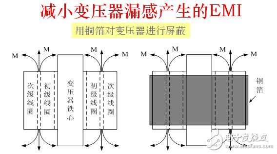
As shown in Figure 4, the shielding of the transformer is mainly to reduce the leakage inductance of the transformer and cause electromagnetic induction interference to the surrounding circuits and external electromagnetic interference. In principle, the non-magnetic material does not directly shield the leakage flux, but the copper foil is a good conductor. When the alternating leakage flux passes through the copper foil, eddy current is generated, and the magnetic field direction generated by the eddy current Just in the opposite direction of the leakage flux, part of the leakage flux can be cancelled, so the copper foil can also shield the magnetic flux.
Countermeasure 5: Using two-wire transmission and impedance matching
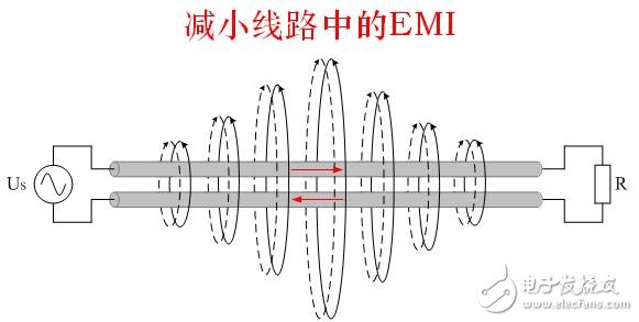
Figure 5
As shown in Figure 5, if two adjacent wires have the same magnitude of current and opposite current directions, the magnetic lines of force they generate can cancel each other out. For circuits with relatively serious interference or relatively easy to be interfered with, try to use two-wire transmission signals. Do not use public ground to transmit signals. The smaller the common ground current, the smaller the interference. When the length of the wire is equal to or greater than a quarter wavelength, the line transmitting the signal must consider impedance matching. The unmatched transmission line will generate standing waves and generate strong radiation interference to the surrounding circuits.
Countermeasure 6: Reduce the area of ​​the current loop
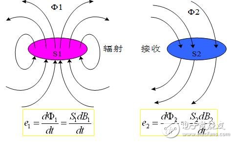
Figure 6
As shown in Fig. 6, the magnetic field radiation interference is mainly generated by the magnetic flux generated by the high-frequency current loop flowing into the receiving circuit. Therefore, the area flowing through the high-frequency current loop and the area of ​​the receiving circuit should be minimized. Where: e1, Φ1, S1, B1 are the electromotive force, magnetic flux, area, and magnetic flux density generated in the radiation current loop respectively; e2, Φ2, S2, and B2 are the electromotive force, magnetic flux, and area generated in the radiation current loop, respectively. Magnetic flux density.
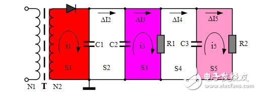
Figure 7
The current loop radiation is explained in detail below with reference to FIG. As shown in the figure, S1 is the rectified output filter circuit, C1 is the energy storage filter capacitor, and i1 is the loop high frequency current. This current is the largest in all current loops, and the magnetic field interference generated is also the most serious. The area of ​​S1 should be minimized. .
In the S2 loop, there is basically no high-frequency loop current, I2 is mainly the power supply ripple current, and the high-frequency component is relatively small, so the area of ​​S2 is basically not considered. C2 is the energy storage filter capacitor, which provides energy for the load R1. R1 and R2 are not pure load resistors, but high-frequency circuit loads. The high-frequency current i3 is basically provided by C2. The position of C2 is relatively important. The connection location should be considered to minimize the area of ​​S3. There is also an I3 in S3, which is mainly the power supply ripple current and a small amount of high frequency current components. In the S4 loop, there is basically no high-frequency loop current. I4 is mainly the power supply ripple current, and the high-frequency component is relatively small, so the area of ​​the S4 is basically not considered. The S5 loop is basically the same as the S3 loop, and the current loop area of ​​the i5 should be as small as possible.
Countermeasure 7: Do not use multiple loops to supply power in series
Several current loops in Figure 7 are connected in series to supply power, which is prone to current common mode interference, especially in high frequency amplifier circuits, which generate high frequency noise. The reason for current common mode interference is: ?I2 = ?I3+ ?I4+ ?I5
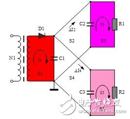
Figure 8
In Figure 8, the various current loops are separated from each other and connected in parallel. Each current loop is independent and does not generate current common mode interference.
Countermeasure 8: Avoid interference signals generating resonance in the circuit
  
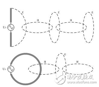
Figure 9
As shown in Figure 9, one pole of the common mode antenna is the entire circuit board, and the other pole is the ground wire in the connection cable. The most effective way to reduce radiated interference is to shield the entire board and ground the case. The cause of electric field radiation interference is that the high frequency signal charges the conductor or the lead, and the length and surface area of ​​the conductor should be minimized. The reason for the magnetic field interference is that high-frequency current flows in the conductor or the loop, and the length and area of ​​the current loop in the circuit board should be minimized. The higher the frequency, the more severe the electromagnetic radiation interference; when the length of the carrier fluid can be compared with the wavelength of the signal, the interference signal radiation will increase.
When the length of the carrier fluid is exactly equal to an integer multiple of a quarter of the wavelength of the interfering signal, the interfering signal will resonate in the circuit, and the radiation interference is the strongest. This situation should be avoided as much as possible.
Seeing here, do you feel that the eight-step walk, the conduction interference is under control? Finally, the spectrum of various interference pulse waveforms is attached for your reference (Figure 10). Any non-sinusoidal wave can be seen as a superposition of a number of signals with different rise and fall rates (or sine waves of different frequencies) superimposed on each other. The intensity of electromagnetic radiation is proportional to the rate of change of voltage or current.
Spectrum of various interference pulse waveforms:
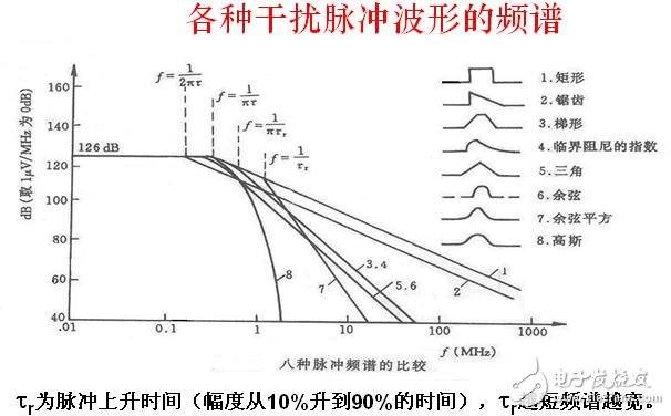
Figure 10 (Cynthia)
Fsr Sensor,Force Sensing Weight Sensor,Fsr 400 Sensor,Pen Fsr Flex Sensor
Dongguan Nanhuang Industry Co., Ltd , https://www.soushine-nanhuang.com