1. The generation and suppression principle of surge voltage
In electronic systems and network lines, it is often subject to external transient over-voltage interference. These interference sources mainly include: operating overvoltage caused by switching on inductive load or starting and stopping high-power load, line fault, etc.; due to natural phenomena such as lightning The thunder of lightning. This overvoltage (or overcurrent) is called a surge voltage (or surge current) and is a type of transient disturbance. Surge voltage can seriously jeopardize the safe operation of electronic systems. Eliminating surge noise and preventing surge damage has always been a core issue related to the safe and reliable operation of electronic equipment. In order to prevent the surge voltage from damaging the electronic equipment, the shunt defense measures are generally adopted, that is, the surge voltage is short-circuited with the earth in a very short time, so that the inrush current is flown into the ground to achieve the purpose of weakening and eliminating overvoltage and overcurrent. Therefore, it plays a role in protecting the safe operation of electronic equipment.
2 Surge voltage suppression device classification Surge voltage suppression devices can be basically divided into two types. The first type is a crow bar device. Its main feature is that the residual voltage after the breakdown of the device is very low, so it not only facilitates the rapid release of the surge voltage, but also greatly reduces the power consumption. In addition, the leakage current of this type of device is small, and the capacitance between the devices is small, so the influence on the line is small. Commonly used crowbar devices include gas discharge tubes, air gap surge protectors, silicon bidirectional symmetric switches (CSSPD), and the like.
The other type is a clamp protector, that is, after the breakdown of the protection device, the voltage across the terminal is maintained at the breakdown voltage and no longer rises, and the protection is provided by clamping. Commonly used clamp protectors are zinc oxide varistor (MOV), transient voltage suppressor (TVS) and the like.
3 Structure and basic principle of gas discharge tube The gas discharge tube is made of ceramic sealed package. The inside is composed of two or several metal electrodes with gaps, which are filled with inert gas (argon or helium). The basic shape is shown in Figure 1. . When the voltage applied to the ends of the two electrodes reaches the breakdown of the gas in the gas discharge tube, the gas discharge tube begins to discharge and changes from high resistance to low resistance so that the voltage across the electrodes does not exceed the breakdown voltage.

(a) Type BB (b) Type BBS Figure 1 Basic shape of gas discharge tube
4 Gas discharge tube and other surge suppression device parameters comparison 1) spark gap (Arc chopping)
For two electrodes shaped like horns, there is a short distance between each other. When the potential difference between the two electrodes reaches a certain level, the gap is broken down by the spark discharge, thereby releasing the overcurrent into the ground.
Advantages: strong discharge capacity, large flow capacity (can achieve 100kA or more), and low leakage current;
Disadvantages: high residual voltage (2 ~ 4kV), slow reaction time (≤ 100ns), followed by current (freewheeling).
2) Metal oxide varistor (Metal oxside varistor)
At a certain temperature, the conductivity of the device increases sharply with increasing voltage. It is a metal oxide semiconductor nonlinear resistor containing zinc oxide as a main component. When there is no overvoltage, it is in a high resistance state. Once the voltage is overvoltage, the voltage is immediately limited to a certain value, and the impedance is abruptly changed to a low value.
Advantages: large flow capacity, low residual voltage, fast reaction time (≤50ns), no follow current (freewheeling);
Disadvantages: The leakage current is relatively large and the aging speed is relatively fast.
3) Transient voltage suppressor
Also known as a Zener diode, it is a device specifically designed to suppress overvoltage. The core part is a PN junction with a large cross-sectional area, and the PN junction has a strong pulse absorption capability when operating in an avalanche state.
Advantages: low residual voltage, high precision of operation, fast reaction time (<1ns), no follow current (freewheeling);
Disadvantages: poor flow resistance, small flow capacity, generally only a few hundred amperes.
4) Gas discharge tube
The gas discharge tube can be used for surge protection in data lines, cable TV, AC power supply, telephone system, etc. The general device voltage ranges from 75 to 10000V, and the peak current withstand voltage is 20000A, which can withstand discharges of up to several kilojoules.
Advantages: large flow capacity, high insulation resistance and low leakage current;
Disadvantages: high residual voltage, slow reaction time (≤100ns), low operating voltage accuracy, follower current (freewheeling).
The common feature of various surge suppression devices is that the device exhibits high impedance below the threshold voltage. Once the threshold voltage is exceeded, the impedance drops sharply, which has a certain inhibitory effect on the spike voltage. However, each has its own disadvantages. Therefore, depending on the specific application, one or a combination of the above devices is generally used to form a corresponding protection circuit. The parameter comparisons of various surge suppression devices are listed in Table 1.
Table 1 Comparison of several commonly used surge suppressor parameters

Gas discharge tube varistor surge suppression diode type sled bar clamp clamp reaction time <1μs<50ns<1ns
Typical capacitance / pF1500 ~ 500050
Leakage current <1pA5~10μA200μA
Maximum discharge current / A (8 × 20μs waveform) 20000650050
5 Main parameters of gas discharge tube 1) Reaction time refers to the time from the applied voltage exceeding the breakdown voltage to the breakdown phenomenon. The reaction time of the gas discharge tube is generally in the order of μs.
2) Power capacity refers to the maximum energy that a gas discharge tube can withstand and dissipate. It is defined as the current that can withstand and dissipate under a fixed 8×20μs current waveform.
3) Capacitance refers to the capacitance between the two poles of a gas discharge tube measured at a specific 1 MHz frequency. The gas discharge tube has a small capacitance, generally ≤ 1 pF.
4) DC breakdown voltage When the applied voltage rises at a rate of 500 V/s, the voltage at which the discharge tube generates a spark is the breakdown voltage. Gas discharge tubes have a variety of DC breakdown voltages of different specifications, the value of which depends on factors such as the type of gas and the distance between the electrodes.
5) Temperature range The operating temperature range is generally between -55 ° C and +125 ° C.
6) The current-voltage characteristic curve is taken as an example of the CG2-230L gas discharge tube of the American Kelai Electronics Co., Ltd., as shown in Fig. 2.
7) Insulation resistance refers to the gas discharge tube resistance measured when externally applied 50 or 100V DC voltage, generally >1010Ω.

Figure 2 Current-voltage characteristic curve
6 Application examples of gas discharge tubes 1) Lightning protection applications for various communication devices such as telephones/fax machines are shown in Figure 3. Features low current, high continuous power, no leakage current, high reliability.

Figure 3 lightning protection application of communication equipment
2) Suppression circuit composed of a combination of a gas discharge tube and a varistor Fig. 4 is a surge suppression circuit composed of a combination of a gas discharge tube and a varistor. Since the varistor has a fatal disadvantage: it has an unstable leakage current, and the varistor with poor performance can be heated and self-exploded due to the large leakage current. To solve this problem, a gas discharge tube is inserted between the varistor. However, this has the disadvantage that the reaction time is the sum of the reaction times of the devices. For example, the reaction time of the varistor is 25 ns, the reaction time of the gas discharge tube is 100 ns, and the reaction time of R2, G, and R3 of FIG. 4 is 150 ns. To improve the reaction time, the R1 varistor is added, so that the reaction time can be 25ns.

Figure 4 Gas discharge tube and varistor combined application
3) Application of gas discharge tube in integrated surge protection system The surge protection system required for automatic control system is generally composed of two or three stages. With the characteristics of various surge suppression devices, reliable protection can be realized. The gas discharge tube is generally placed at the input end of the line as a first-level surge protection device to withstand large surge currents. The secondary protection device uses a varistor that responds faster in the μs time range. For highly sensitive electronic circuits, a three-level protection device, TVS, can be used to respond to surge voltages over the ps-level time range. As shown in Figure 5. When a surge such as lightning arrives, the TVS starts first, and the instantaneous overvoltage is accurately controlled to a certain level; if the surge current is large, the varistor starts, and a certain surge current is discharged; the voltage at both ends will be It is increased until the discharge of the gas discharge tube of the preceding stage is pushed, and a large current is discharged to the ground.
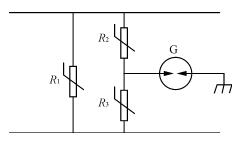
Figure 5 three levels of protection
7 Conclusion Various electronic systems, as well as communication networks, are often subject to external electromagnetic interference, mainly from the transient process of power lines, lightning strikes, and cosmic radio. These disturbances can cause system malfunctions or even hardware damage. In order to solve these problems, to comprehensive prevention and protection measures, we need to find the root cause of the problem and then use appropriate surge suppression devices to solve it.
12W Medical Power Supply,Breathing Machine,Respirator Power Supply,Anesthesia Machine Power Supply
Shenzhen Longxc Power Supply Co., Ltd , https://www.longxcpower.com