Thermoelectric temperature sensors are widely used in industrial applications due to their durability and accuracy. However, they must be carefully selected based on the environment in which they will operate. For example, standard metal thermocouples are not suitable for oxidizing or corrosive environments, while precious metal thermocouples should not be used in reducing atmospheres. To protect the sensor from damage, a stainless steel protective sleeve with a ceramic insulating tube is typically used to isolate the conductor parts, except at the solder joint. The sleeve is sealed at one end and has a terminal at the other for connection to wires or extension cables, as shown in Figure 2.3.5(d).
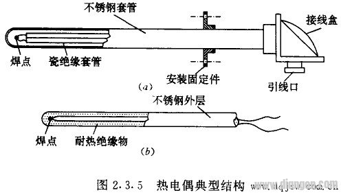
An alternative manufacturing method involves surrounding the thermocouple materials with ceramic powder and then forming them into a stainless steel tube, creating what is known as an "armored thermocouple." This design is shown in Figure 2.3.5(b) and provides better mechanical strength and protection against environmental damage.
Despite the excellent insulation properties of ceramics, high-temperature environments can still lead to leakage currents. This can cause common-mode interference voltages on the thermocouple signal lines, which may affect the performance of sensitive instruments or computers. Therefore, it's crucial to take this into account when designing measurement systems.
The thermal inertia caused by the protective sleeve and ceramic tube can increase the time constant of the thermocouple, making it less responsive to rapid temperature changes. In scientific experiments where quick response is essential, it's often preferable to use exposed thermocouples directly in contact with the medium, especially those with smaller diameters that react more quickly.
How Thermoelectric Temperature Sensors Work
The output of a thermocouple is a small DC electromotive force (EMF), typically up to tens of millivolts. This EMF arises from two physical effects:
(1) Contact Electromotive Force: When two different conductors (A and B) are joined, a difference in free electron density leads to electron diffusion at the junction, creating a contact EMF. This EMF depends on both the material and the temperature, and is denoted as eAB(t).
(2) Temperature Difference Electromotive Force: When a single conductor (A) has a temperature difference between its ends, a non-uniform distribution of free electrons causes a thermoelectric EMF. This is represented as eA(t, t0), where t and t0 are the temperatures at each end of the conductor.
When conductors A and B are joined to form a closed loop, and one junction is at temperature t while the other is at t0, four EMFs are generated: eAB(t), eAB(t0), eA(t, t0), and eB(t, t0). Their algebraic sum is EAB(t, t0), which is used to determine the temperature difference between the two junctions.
In practical measurements, the junction at the higher temperature is called the "hot junction" or "working junction," while the one at the lower temperature is the "cold junction" or "reference junction." To measure the EMF, the cold junction is usually disconnected and connected to a measuring instrument. According to the third-conductor rule, the presence of a third conductor (C) in the loop does not affect the total EMF as long as its ends are at the same temperature.
To maintain accuracy, the cold junction should be kept away from high temperatures. If the thermocouple materials are expensive, compensation wires made of similar thermoelectric properties but cheaper materials can be used to extend the cold junction to a stable location. These wires are flexible and insulated, making them easy to install over long distances.
The polarity of the extension or compensation wire must match that of the thermocouple. Incorrect wiring can lead to errors or even no reading at all. Always double-check connections to ensure proper operation.
Agricultural Drone,Crop Sprayer Drone,Drone Crop Sprayer,Agricultural Sprayer Drone
Xuzhou Jitian Intelligent Equipment Co. Ltd , https://www.jitianintelligent.com