1 Introduction
In recent years, the increase of industrial Ethernet communication rate and the emergence of switched Ethernet technology have greatly improved the communication performance of industrial Ethernet. The reliability testing system for relays proposed in this paper consists of a server and multiple reliability testing devices (clients). The reliability testing device is a necessary means for reliability testing. The server and the reliability detection device transfer data by calling the socket provided by the TCP protocol, which realizes the real-time centralized detection and control of multiple detection devices by the server, which saves manpower and facilitates the analysis and processing of failure test data.
2. Realization method and function of reliability detection device
The detection device mainly completes the fixed number censoring test of the relay sample, records the failure information, and analyzes the detection results [2]. By establishing a connection with the server, the current test status and failure information are uploaded in real time, and the control commands of the server are received.
2.1 Implementation method
In order to meet the needs of the test environment, an industrial control computer is used as the core of the detection device. Two high-performance data acquisition cards are used to collect the contact voltage, which can detect 32 pairs of contacts in two groups at the same time. The two groups of test samples can be relays of different models and different manufacturers. Normally open and normally closed without restriction. It should be noted that when the contact voltage is an AC signal, in order to ensure the calculation accuracy of the effective value of the voltage, the acquisition card must complete at least 320 AD conversions of the 16 acquisition channels in a power frequency cycle, which requires the acquisition card The acquisition rate is very fast, this device uses Advantech's PCL-818HG. Each acquisition card also provides a 20-PIN digital output port, which is used to control the power on and off of the coil circuit of the sample. The test sample contact circuit uses a multi-channel digital output card, and the solid-state relay is used to control the on and off of the two test sample contact circuits. The structural block diagram of the relay reliability detection device is shown in Figure 1.
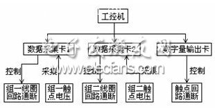
Figure 1 Structure diagram of reliability detection device
If all contacts of a certain test product have reached the maximum number of failures, then in the next test, this test product should be rejected, and the coil circuit and contact circuit of the test product should not be turned on and off to avoid failure. The test sample is dangerous due to long-time power-on [3].
2.2 Realization function
The software of the detection device consists of two parts: one is the real-time detection and processing program, including the setting of test parameters, the storage of test status and failure data, the mathematical analysis of the failure data, the printing of reports, etc. The failure recorded by the detection device The data includes the failure time, the failed test article number, the contact number, the type of contact failure, the contact voltage at the time of failure, and the cumulative number of failures of each contact. Test status and failure information. Figure 2 is the operation interface of the detection device. The menu items represent all the operations that can be achieved. The text display area displays the setting parameters, test status, and failure information when failure occurs. The software is implemented by the method of visual programming language VC ++ 6.0 embedded in assembly language [4].
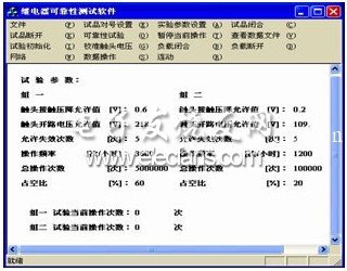
Figure 2 Operation interface of detection device
3. Realization of centralized control
Ethernet only defines the physical layer and the link layer, but at present, the transmission layer and the network layer have been basically unified, and the TCP / IP protocol is generally adopted. Transport layer protocols include UDP protocol and TCP protocol. Whether it is based on UDP protocol or TCP protocol, certain reliability and real-time performance of network transmission must be guaranteed. Because the UDP protocol has the characteristics of simple implementation mechanism and high transmission efficiency, it is mostly applied to high-efficiency real-time systems. But in order to realize the reliability of transmission, it is necessary to adopt some error control mechanisms at the application layer, and these measures are very similar to the transmission mechanism that comes with the TCP protocol. In fact, in many real-time systems, the use of TCP protocol can basically meet the requirements of transmission time, and avoid the cumbersome processing at the application layer [5]. Therefore, in this scheme, the transport layer chooses to use the TCP protocol.
The application layer protocols are not yet unified. This article aims to study a general communication scheme that can be widely applied to multiple applications and multiple application layer protocols.Users can choose different application layer protocols according to their needs, or they can define their own Packet format.
Features
â—† Wide Application
Specialized in Hairdryer Switch with crisp handfeel,clear gears,reliable electrical contact
â—† Easy to install and use
Simple installation, freely turn on or off the load which you want to control.
â—† High Operating Life
Made of high quality polyamide eP(Nylon PA66) material, this sturdy mini boat Rocker Switch is born for anti-corrosion,anti-acid and high resistant with silver terminals.100,000 times of ON/OFF operating life span.
Automotive Rocker Switch,Dual Rocker Switch,Red Rocker Switch,Custom Automotive Rocker Switches
Ningbo Jialin Electronics Co.,Ltd , https://www.donghai-switch.com