Auto Acoustics Modeling Based on AUTOSEA Simulation Software
For many car manufacturers, the complete acoustic modeling design of a car is still a dream. However, acoustic simulation methods are more and more widely used, and are becoming an important design tool dedicated to reducing development time.
Acoustic modeling is often misunderstood as a magic tool that can solve all problems. In fact, so far, acoustic and vibration modeling can only provide important suggestions rather than definitive answers, and must also have the concept of using it as a problem-solving tool during the development and prototype stages.
Because it is not very believed, all the acoustic problems of the vehicle are not taken into account in the design stage, so the acoustic problems appear in the prototype or later. If the experimenter can obtain the FEM (Finite Element Method) model, then the acoustic problem can be considered from the beginning; at the same time, if the designer can understand the true meaning of a measurement report, the problem is easier to solve. Therefore, acoustic modeling should be an additional tool combined with prototype development and problem-solving-oriented. At the same time, related processes can follow the following principle steps.
In the design stage: 1. Obtain a simplified acoustic FEM model; 2. Under the estimated input force, use BEM or SEA method to evaluate the noise level; 3. Calculate whether there will be serious problems in the design stage.
In the prototype stage: 1. Obtain experimental data and isolate noise problems from the prototype; 2. Obtain a cyclic model of each problem and check the input force amplitude; 3. Try possible solutions and simulate the expected results; 4. Check the application of The solution on the prototype; 5. Use the experimental data to improve the solution.
Design method
The following is a case cited from Vibro-AcousTIcs Science Inc. ApplicaTIon Note (vibration acoustics newspaper), which describes the application of AUTOSEA simulation software in the interior noise of the vehicle (see Figure 1).
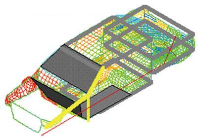
Figure 1 AUTOSEA model of vehicle with subsystem
In terms of interior noise, typical problems are: interior noise level; noise source and transmission path; how to reduce noise level. In order to answer the above questions, it is necessary to import the FEM model of the vehicle. This is a typical coarse mesh model of the "concept stage", which will probably generate 150,000 units, of course, the number of units needs to be reduced to about 50,000. The simplified model must be revised to solve certain problems, and then check whether the original characteristics are still maintained.
It is now possible to assess the noise level of multiple receiving locations in the vehicle using a simplified model (based on the frequency range of interest) using a simplified model. There are two methods to choose from: the FEM-BEM (Finite Element and Boundary Element) method with an upper frequency limit of 200 Hz and the SEA (Statistical Energy Analysis) method of 200 Hz and above. The FEM-BEM method can be applied to structural propagation and air propagation paths, but this method becomes complicated and requires too many elements when the model density increases rapidly, and SEA can give good results when the model density increases .
To identify the source of vibration or noise and the transmission path, the related technology must be used in conjunction with the FEM-BEM method, so that the noise reduction technology may produce results. The SEA method is based on energy transfer calculations to identify the contribution of each source and the efficiency of the acoustic transmission path (see Figure 2).
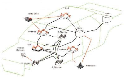
Figure 2 SEA network
By analyzing them one by one, complex problems can be solved more effectively. Here we show the use of AUTOSEA in specific occasions considering the noise of the roof (produced by pneumatic pressure).
First, we import the FEM model and store the material and beam section properties in the database, and then simplify the geometry complexity by creating only NASTRAN roof elements and all SEA substructures (except for the windshield that is visible). We added curved panels to the SEA model to represent the ceiling.
1. Assemble the canopy, windshield and internal cavity and observe the number of modules in the band, because the acoustic cavity increases very quickly.
2. Trace the wave number of the selected subsystem and observe that the coincidence frequency of the glass is much lower than that of the ceiling. In a wide frequency band, the windshield is an obvious radiator.
The angle connecting the roof and the windshield subsystem is close to normal, so energy can only be transferred through moments. Connecting the ceiling and the internal subsystem, the radiation efficiency of the ceiling panel depends on the fixed boundary (such as the general baffle and the ceiling lining respectively increase and decrease the radiation efficiency). The influence of the headliner on the radiation efficiency can be obtained by analyzing and simulating the SEA method or importing the experimental data into the model.
Replace the wind (pneumatic) pressure source with a power source connected to the ceiling subsystem. The spectrum of aerodynamic pressure can be determined by wind tunnel test or road test data, or calculated as a default spectrum. The energy input to the canopy is because the wind noise is large at low frequencies, and will rapidly decrease due to the difference between the structural wave number and the convection wave number. Please note: The other sources of vibration and noise in the model (see Figure 3) are engine noise transmitted through the structure (represented by the vibration measured by the front rail of the vehicle) and airborne tire noise (diffuse sound measured from the bottom surface of the vehicle floor Pressure level said).
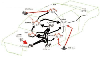
Figure 3 Vibration noise source
If you want to obtain predictable A-weighted sound pressure values ​​for cars, trucks, undercarriages, windshields, and roofs by solving the above network, you may have to notice that the higher measurement level of A-weighted sensors is applicable At frequencies above 500 Hz. If you look at the energy input into the vehicle (for multiple vibration noise sources), you will find that tire noise occupies the frequency range of 250 to 1 000Hz, but in the higher frequency band, the windshield should be responsible for the noise in the vehicle. Too. Therefore, we now have to understand what exactly caused the windshield to vibrate.
The first way is to perform “source ranking†by freezing the internal sound pressure, and then disconnect the wind noise source and the tire noise source and solve all the problems again. The results show that the high-frequency radiation introduced into the windshield of the car is caused by structural excitation caused by engine vibration.
Then reconnect the wind noise source and the tire noise source (the input of the bottom plate mass method is 0.73m2 and 4.5kg), and solve the related problems again to obtain the energy flow at 2 000Hz. As expected, the windshield and instrument panel are the two main sources of noise in the car, but now we are also informed of the structural path transmitted through the upper and lower pillars.
Fetal noise transmission in the frequency range of 500 to 2 000 Hz can be reduced by adding a floor mat. But to characterize the floor mat, a 3-layer sample must be created in the database and added to the tire noise and connectors inside the car. The composition of this component can be tested and adjusted to achieve the maximum effect (within the desired frequency band). The double-wall resonance effect may increase the sound pressure in the car in certain frequency bands, like 250Hz. For this model, other design solutions can also be tested, such as: optimization of floor mats; optimization of internal sound absorption kits (also using the SEA method); changes to the structure of the front section of the vehicle, designed to reduce high-frequency noise caused by engine vibration .
Prototype approach
Once the prototype or some parts of the prototype become available, some preliminary investigations can be carried out, and after obtaining typical data and frequency analysis (in-car noise "listening" meetings), standard measurement procedures can be carried out to convert the data Technical understanding and physiological feelings are combined to determine what is going on.
"Listening" is the key point, in fact, this feature can be added to the measurement using artificial fake head or BHM (Binaural Measurement Microphone of HEAD AcousTIcs).
By paying attention to the noise activity expressed by time and frequency, the acoustic engineer was able to focus on some specific noise he noticed, so as to use HEAD AcousTIc's SQ-LAB to strengthen the noise or suppress other false phenomena. For example, we can listen and compare the original recording and the filtered version of the same recording simultaneously; filtering means to reduce the amplitude of a specific component of the sound and feel the sound changes. This sensory analysis has an extraordinary effect on the establishment of cause and effect, the identification of a single noise source, and the identification of possible transmission paths of structures & media.
Normally, the vehicle is tested in both accelerated and stationary states. The first step is usually to find problems on the test track, such as the maximum A-level in the car, the critical area of ​​the roar phenomenon, the noise composition, the speed and speed of the vehicle, and the sound quality. The listening and analysis of the drive test will provide hints to the definition of the next "test plant", which includes the identified problems, priorities and investigation steps.
The acoustic model must first be investigated, so that the validity of the investigation can be verified more quickly, and experimental verification can be advanced with greater confidence. Perhaps artificial modification of the acoustic model does not always give the desired result, because the simulation tool is not perfect, but in any case, some suggestions to guide the experiment can still be obtained. It is this parallel investigation of acoustic models and prototypes (bilateral exchange of information) that accelerates the exploration of possible solutions and their verification of specific noise problems.
Modal analysis
In order to outline the guiding significance of acoustic models for experimental testing, we will explain some representative tasks performed in a real case of a light truck.
The experimental modal analysis of the whole vehicle is not easy, and its inspection effect on the FEM model is not obvious. The problem is that the excitation of the suspension and the structure alternately shows high damping for the high mode and non-linearity for the low mode. Since the acoustic model report shows the type of problem that needs to be investigated, it is relatively more efficient to perform modal analysis on substructures (windows, roofs, doors, etc.). Try to make the excitation point as close as possible to the real situation, such as: engine or cockpit suspension, roof canopy distribution force, etc.
Acoustic mode
The experimental determination of the acoustic mode in the car has two purposes: one is to check the theoretical mode to improve the acoustic model; the other is the damping measurement (the value of the experimentally determined damping is attributed to the acoustic material, dashboard and seat). The problem here is the acoustic excitation of the internal cavity, because some types of speakers used do not support receiving any information about the excitation force, such as system input. One possibility is to use standing wave tubes, which are commonly used to determine the acoustic properties of materials. One end of the standing wave tube opening is installed in the window (open), and the other end is equipped with a speaker. Two microphones are installed in the longitudinal direction. By measuring the transfer function between the two microphones, the energy flowing into the cabin from the other end of the tube can be derived.
Input force
The drive test is used for both noise and vibration measurement; while noise measurement is mostly concerned with the noise level in the car, the vibration measurement of the engine mount gives the amplitude and spectrum of the input force related to the noise transmitted by the structure. By inserting the measured force into the acoustic model, it can be more accurately concluded that the noise calculation is based on the input vibration.
As for the air-borne input forces, such as the acoustic radiation of the engine, a different method (depending on whether the FEM model of the engine is available) is quite necessary. In most cases, we cannot know this at the design or prototype stage, so it is interesting to determine the acoustic model of the engine through experiments. This process is actually very self-analyzing: mapping the hypothetical sound pressure level SPL on the hypothetical surface around the engine under test can define the distribution of sound pressure and the relationship between phase and frequency. When the same distribution is given, an equal acoustic source acoustic model is obtained by lagging least squares estimation.
An acoustic model of an engine requires 10 to 20 basic pistons with radiating area (weighted engine geometry). This process is easy to understand, but requires good techniques for implementation: First, a multi-channel measurement system must be established (with sufficient microphones to obtain the phase relationship and some reference microphone positions); second, a critical speed must be used as a standstill in the measurement Conditions, and this information can only be obtained through analysis of drive tests and "listening" meetings; moreover, this information can be inserted into the vehicle's acoustic model as a true airborne input force, and the noise level in the vehicle will be recalculated .
Conclusion
Vehicle acoustics research is the work of a team, not the application of personal feelings and expert opinions. There are several possible methods in both the design and prototype stages, and there are many possible sources of noise in reality, but there is no single exact procedure that is applicable to every subject.
If you want to make full use of the advantages of modern computing systems, you should follow some of the simplest methods to simplify the complex total project into independent problem groups. Do n’t get lost in treating the vehicle ’s acoustics as a general problem, as the old saying goes, “Do n’t just see the forest but not the treesâ€.
For example, from the beginning of the design stage, the simplified method should be introduced into the vehicle's acoustic research, and when the prototype is available, the acoustic model must be adjusted in conjunction with experimental data. Once the experiment identifies the noise problem, the possible solution should be run multiple times on the acoustic model adjusted with the experimental data, because the changes and verification on the model are faster than the changes and verification on the prototype car And cheap.
From an acoustic point of view, the optimal results and the rational development of vehicles are based on this data exchange between experimenters and modelers.
Guangzhou Ehang Electronic Co., Ltd. , https://www.ehangmobile.com