1. Signal control circuit composed of CD4047 and CD4027
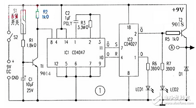
The control part is composed of two chips, CD4047 and CD4027. The CD4047 (IC1) is connected to the positive edge triggered monostable multivibrator circuit mode to set and reset the CD4027 (IC2). The pulse width at the output of IC1 depends on the values ​​of R3 and C2 connected between pins 1 and 2.
under normal circumstances.
The gate is closed,
At this time, the reed switch S1 is closed, the transistor T1 is turned on, the one-shot circuit IC1 is kept in the standby state, and the output pin 10 is at a low potential.
When the gate is opened,
The reed switch S1 is disconnected and T1 stops conducting. The collector is sent to IC18 from the low-to-high potential change to trigger IC1, and the 10th pin sends a positive pulse with a duration of about 10 seconds. At the same time, its complementary leg 10 goes low. The output of IC1 is used to set and reset IC2.
IC2 is a low-power dual JK master-slave flip-flop chip that changes its state based on the rising edge of the clock signal. IC2 is connected such that when its reset pin 4 receives a high potential pulse, its output pin Q goes high; and when the set leg 7 receives a high potential pulse, its Q output pin goes low, and its complementary leg 2 goes high. This causes LED 2 to illuminate and drive transistor T2 to conduct, activating the subsequent alarm circuit.
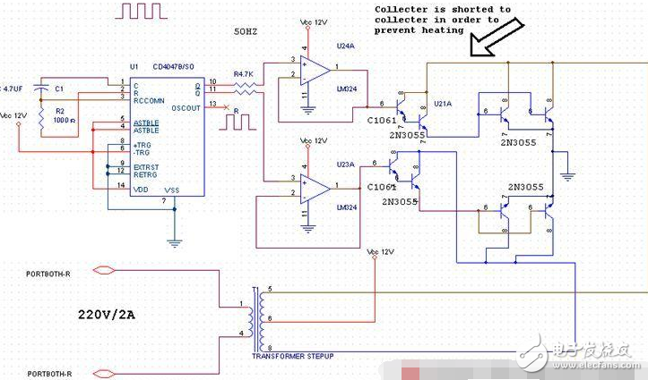
2, AC inverter
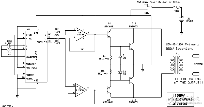
A 220V AC 50Hz or 60Hz square wave signal is output from the car battery input 12VDC.
The main parts are IC IC4040 and LM358 integrated circuits and transistors 2SC1061 and 2N3055.
The transformer secondary is 220V 12v-012v primary.
Current 3A is output power exceeding 100w
note:
C1 = 0.1uf metallized film capacitor with 5% tolerance.
RR1 = 47k 50Hz output, 39k is the output.
3, inverter 100W 12V to 220V by transistor
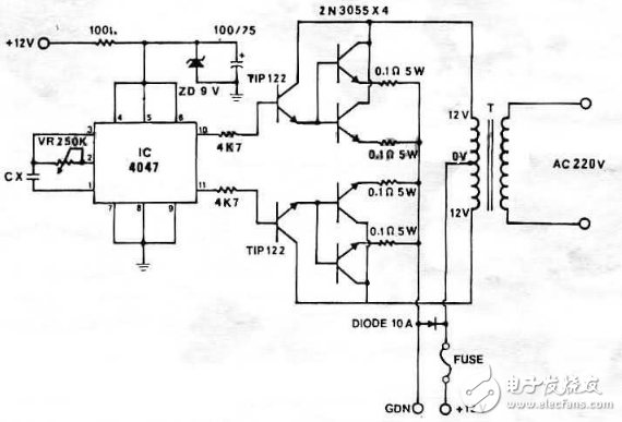
Inverter 100w IC 4047 + 2N3055 (PCB)
Inverter selects NE555, 2N3055 12V to 220V 300W
Inverter selects NE555, 2N3055 12V to 220V 300W
300w DC24V AC220V NE555, ca3130, 15003 for inverter
500w 2N3055 for 12v 220V inverter
Inverter 100w IC 4047 + 2N3055 (PCB)
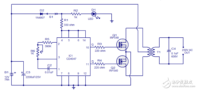
4. Circuit diagram of the inverter of CD4047 and IRF540 MOSFET
Below is a simple 100 watt circuit diagram of an inverter using IC CD4047 and IRF540 MOSFETs. The circuit is simple, low cost, and can even be assembled with a veroboard.
The CD4047 is a low power CMOS non-stable/monostable multivibrator IC. Here, it is connected to the production of 0.01S 180 degree phase IC pins 10 and 11 two pulse sequences as an unsteady multivibrator. The gate of pin 10 connected to pins Q1 and 11 is connected to the gate of Q2. Resistors R3 and R4 prevent ICs from loading the respective MOSFETs. When the 10th pin is high, the first half of the current flowing through the upper half of the transformer accounts for the positive half of the output AC voltage. When the 11th pin is high in the second quarter, the current flows through the lower half of the transformer primary in the opposite direction, and it outputs a negative half account of the AC voltage.
Circuit diagram:
Precautions:
B1 can be a 12V / 6AH lead-acid battery.
Q1 and Q2 must be fitted with appropriate heat sinks.
The T1 can be a 9-0-9 V elementary, middle school, 230V 150VA transformer.
5, based on CD4047 12V to 220V inverter circuit diagram
12V to 220V inverter circuit diagram
How to calculate the rating of the transformer
The basic formula is: power P = voltage V & TImes; current I
For example, if we want to output a 220V voltage of 220W, then we need 1A of output current. Then at the input, a voltage of 12V requires at least 18.3A because: 12V * 18.3A ≈ 220W. Transformer efficiency losses are not considered here.
A color filter is an Optical Filter that expresses colors. It can precisely select the small range of light waves to be passed, while reflecting off other undesired wavelengths. The color filter is usually installed in front of the light source, so that the human eye can receive the saturated light of a certain color. There are infrared filters, green, blue, etc. Compared with UV filters and VD filters, it is a general term for colored filters. Such as contrast filter, color separation filter, LB filter, etc.
Colored glass exhibits different colors due to its absorption in the visible light waveband. Colored glass is widely used in laser protection, industrial measurement and environmental measurement instruments.
Black Glass Filter,Red Glass Filter,Yellow Glass Filter,Green Glass Filter
Bohr Optics Co.,Ltd , https://www.bohr-optics.com