Communication, according to the traditional understanding, is the transmission and exchange of information. For the single-chip microcomputer, communication is closely combined with sensors, memory chips, peripheral control chips and other technologies, becoming the "nerve center" of the entire single-chip system. Without communication, the functions implemented by the microcontroller are limited to the microcontroller itself, and it is impossible to obtain useful information through other devices, and it is impossible to tell other devices the information generated by itself. If the MCU communication is not handled well, the degree of cooperation with the peripheral devices is limited, and eventually the entire system cannot complete the powerful functions, which shows the importance of the MCU communication technology. UART (Universal Asynchronous Receiver/Transmitter) serial communication is the most commonly used communication technology for single-chip microcomputers. It is usually used for communication between single-chip microcomputer and computer and between single-chip microcomputer and single-chip microcomputer.
1. The basic concept of the serial port
1.1 UART - Serial Asynchronous Receiver Universal Asynchronous Receiver/Transmitter
Serial/parallel (after class)
Asynchronous/synchronous: 'The difference between the two asynchronous/synchronous communications' (supplement)
'simplex/half duplex/full duplex:
Simplex: Data can only be transmitted in one direction at any time
Half-duplex: Data can be transmitted in both directions, and any one time can only be transmitted in the same direction
Full duplex: data can be transmitted in both directions simultaneously
1.2 Serial Communication Standard
RS232 (Electronic Industry Protocol EIA) - The most commonly used 'serial interface standard'
The 'electrical characteristics' are specified:
Logic 0, +3 v ~ +15 v, SPACE
Logic 1 , - 3 v ~ - 15 v, MARK
The 'mechanical characteristics' are specified:
Transmission distance "10 m
TTL level, computer internal level (CPU):
Logic 0, low level "0.8 v
Logic 1, high level 2.4 v
Important parameters of serial asynchronous communication:
》》Number of data bits: 5 ~ 8 bit (8 bit / frame data is fixed at the end of the development board)
》》Verification: odd parity, even parity, no parity
》》Stop width: 1~2bit
"" communication rate: bps (bit per second - transmission bit per second) 'baud rate unit'
There are two ways to complete serial communication:
1) One way: The program running in the arm core directly operates the GPIO pins just like the LEDs to form the timing of serial asynchronous transmission and reception of data.
2) Another way: U5 controller is integrated in S5P6818. Mode 1) The process of pure software implementation communication can realize the communication timing by using the combination of software and hardware, thus simplifying software programming.

In general, the basic steps for writing a serial communication program are as follows:
1. Configure the serial port to mode 1.
2. Configure timer T1 to be mode 2, that is, automatic reload mode.
3. Calculate the initial values ​​of TH1 and TL1 according to the baud rate. If necessary, you can use PCON to double the baud rate.
4. Turn on the timer control register TR1 to let the timer run.
It is also important to note here that when using T1 as the baud rate generator, do not enable the T1 interrupt again.
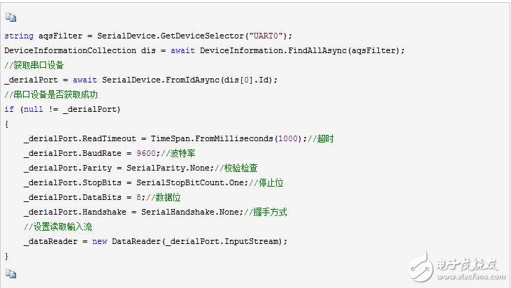
Let's first look at the program code when the IO port analog serial communication is directly changed to use the hardware UART module, to see if the program is much simpler, because most of the working hardware modules are done for us. The program function is exactly the same as the IO port simulation.
#include 《reg52.h》
Void ConfigUART(unsigned int baud);
Void main()
{
ConfigUART (9600); //Configure baud rate is 9600
While (1)
{
While (!RI); //waiting to receive completion
RI = 0; //Clear the receive interrupt flag bit
SBUF = SBUF + 1; //Received data is +1, sent back
While (!TI); //waiting to send complete
TI = 0; // Clear the transmit interrupt flag bit
}
}
/* Serial port configuration function, baud-communication baud rate*/
Void ConfigUART(unsigned int baud)
{
SCON = 0x50; //Configure the serial port as mode 1
TMOD &= 0x0F; //Clear the control bit of T1
TMOD |= 0x20; //Configure T1 to mode 2
TH1 = 256 - (11059200/12/32)/baud; // Calculate the T1 reload value
TL1 = TH1; //The initial value is equal to the reload value
ET1 = 0; // disable T1 interrupt
TR1 = 1; //Start T1
}
Of course, this program is still written in the main loop waiting for receiving the interrupt flag bit and sending the interrupt flag bit. In actual engineering development, of course, this can not be done, we just want to use the intuitive comparison to tell The hardware modules of the students can greatly simplify the program code, so the serial port interrupt is used when actually using the serial port. Let's look at the program implemented by the interrupt. Please note that because the receiving and sending triggers the same serial port interrupt, in the serial port interrupt function, you must first determine which type of interrupt, and then make the corresponding processing.
#include 《reg52.h》
Void ConfigUART(unsigned int baud);
Void main()
{
EA = 1; //Enable total interrupt
ConfigUART (9600); //Configure baud rate is 9600
While (1);
}
/* Serial port configuration function, baud-communication baud rate*/
Void ConfigUART(unsigned int baud)
{
SCON = 0x50; //Configure the serial port as mode 1
TMOD &= 0x0F; //Clear the control bit of T1
TMOD |= 0x20; //Configure T1 to mode 2
TH1 = 256 - (11059200/12/32)/baud; // Calculate the T1 reload value
TL1 = TH1; //The initial value is equal to the reload value
ET1 = 0; // disable T1 interrupt
ES = 1; //Enable serial port interrupt
TR1 = 1; //Start T1
}
/* UART interrupt service function */
Void InterruptUART() interrupt 4
{
If (RI) //received bytes
{
RI = 0; // Manually clear the receive interrupt flag bit
SBUF = SBUF + 1; //Received data is sent back to +1, the left side is sent SBUF, and the right side is received SBUF
}
If (TI) // byte sent
{
TI = 0; // Manually clear the transmit interrupt flag
}
}
You can experiment to see if it is consistent with the previous implementation of IO port analog communication, and the main loop is completely empty, we can add other function code at will.

Product advantages:
1. Stylish, portable, practical and convenient home charger
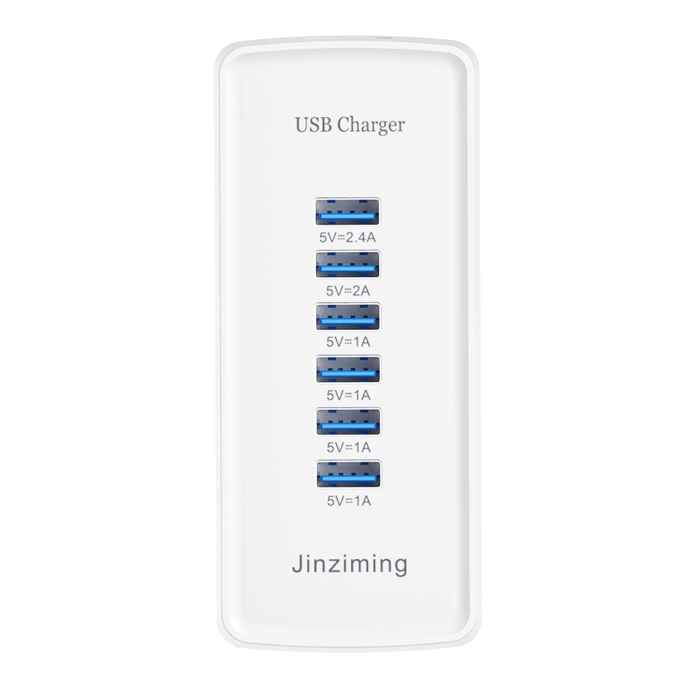
2. 6-port USB emergency charger, which can be used safely for tablet computers and can charge 6 devices at the same time
3. Built-in IC chip and fuse, protection: over current, over voltage, short circuit protection
4. The latest release, new design, beautiful appearance, high efficiency and energy saving, the best alternative to the original charger
5. Chargers for MP3, MP4, GPS, PDA, e-books, mobile phones, digital cameras, tablets, etc.
Features
(1) Overcharge protection
(2) Over discharge protection
(3) Short circuit protection
(4) Voltage stabilization protection.
(5) Automatic identification of mobile phone current protection.

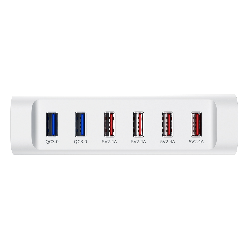
1. Connect up to 6 USB devices at a time, and each device will receive a unique and tailor-made charge. The maximum output power of QC3.0 is 18W, which can optimize the charging of all devices.
2.2QC3.0+4 ports total 6 charging ports, which can charge 6 devices with a total power of 84W at the same time
3. With multiple protection safety systems, the product will automatically adjust the charging current according to the needs of the device being charged. Automatically detect and adjust the charging current to charge your device at the fastest speed.
One machine for multiple uses
The USB charger can charge 6 devices at the same time, and the smart recognition technology will detect and provide the best charging level for each of your devices.
The maximum output current of a single USB port is 2.4A. 2QC3.0 has 6 charging ports, which can charge 6 devices at the same time without causing shunting or reducing power. The USB charger can quickly charge your devices. Smartphones and tablets can receive up to 2.4 amps of current, so you can use the device as you like while charging.
Over-current, over-charge, and short-circuit protection will make charging safe, without any risk of overheating or damaging the device. Passed CE/FCC/ROSH/PSE/CCC certification. Through safety certification to ensure safe use.
Usb Charger,Usb C Charger,Usb C Power Adapter,Portable Usb Charger
Shenzhen Jinziming Electronic Technology Co.,LTD , https://www.powerchargerusb.com