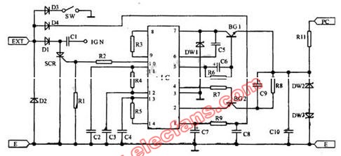
Motorcycle electronic igniter circuit diagram: The alternating current generated by the EXT magnetomotor is rectified by D1, stored in C1, rectified by D4, and filtered by R9, C7, and C8. When grounded, the electronic igniter does not ignite). The PC touches the hair coil, and the trigger voltage is input from the pins 2 and 7 of the IC through BGI and BGZ, so that the trigger pulse is generated on pin 10, and the voltage divided by R1 and R2 is added to the control pole of the SCR to make it conductive. C1 discharges through SCR, makes IGN produce higher voltage, discharges the spark plug through the ignition coil, the engine works. The circuit is provided with a time adjustment circuit, which can automatically synchronize and follow the adjustment of the ignition timing with the engine speed, so that the engine always ignites at the best time required by its speed.
Lithium Polymer Charger,36V Lithium Battery Charger,36V Bike Lithium Battery Charger,36V Bicycle Lithium Battery Charger
Changxing Deli Technology Co., Ltd. , https://www.delipowers.com