Reduce the number of chips used, ideal for broadband applications: MAX2721 direct frequency conversion upconverter
Important: This article describes the application of the MAX2721 in a broadband transmitter. Introduced a 2.3GHz WCDMA application circuit. Direct conversion at 2.4 GHz is difficult because I / Q signal amplitude and phase matching must be very ideal. The MAX2721 generally has ± 0.2 dB and ± 1 degree matching errors, 31 dB carrier suppression, 35 dB sideband suppression, and 32 dB Gain control range. The driver amplifier outputs + 12.5dBm at the 1dB compression point. From the performance data summary, it can be seen that the EVM of the 2300MHz WCDMA application is 6.6%.
More information
In order to provide high-quality multimedia services, the field of wireless communications is experiencing a demand for higher data rates and channel capacity. These systems often require spectrum spreading techniques, such as the higher rate spread of direct sequence spread spectrum (DSSS) systems in 2.4GHz band wireless LAN applications that comply with IEEE® 802.11b. Third-generation systems such as 3GPP and Wireless Local Loop (WLL) also use WCDMA (Wideband Code Division Multiple Access) modulation schemes with channel spacings of 5MHz and 10MHz, respectively.
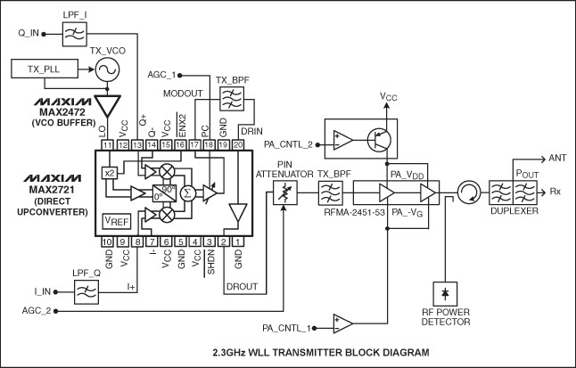
The MAX2721 direct upconverter quadrature modulator IC is specifically designed to simplify the 2.4GHz band wideband transmitter. Since there is no need to use IF oscillator and synthesizer, it has lower system cost than IF-based transmitter structure. In this application note, the system performance of a complete direct upconversion WCDMA transmitter for 2.3GHz WLL is given, and a new, simple, and elegant solution that can replace the IF-based transmitter is shown. The block diagram of the transmitter is shown in Figure 1. 
Figure 1. Block diagram of the MAX2721 direct conversion transmitter
The MAX2721 I / Q input port has a -1dB bandwidth of 20MHz and an impedance of 1kΩ. The -1dB input bandwidth obtained by the experiment is 44MHz at 300Ω and 250MHz at 50Ω. Therefore, the MAX2721 is sufficient for any new wireless standard that requires wide baseband bandwidth.
Direct frequency conversion modulation in the 2.4GHz band poses many challenges for RF IC designers, especially the I / Q amplitude, phase balance, and quadrature accuracy required by the LO signal. Generally, quadrature modulators work at IF frequencies below 300MHz. At higher operating frequencies, amplitude and phase matching will become more difficult. Inadequate sideband suppression and carrier suppression may be caused by an incomplete quadrature LO signal at 2.4 GHz or amplitude imbalance and DC offset. Error Vector Magnitude (EVM) can well describe vector magnitude and phase accuracy. Assuming that the modulated I / Q signal from the DSP has the smallest amplitude / phase error and DC offset, the MAX2721 generally has a gain and phase imbalance of ± 0.2dB and ± 1.0 degrees. The carrier suppression that can be achieved is 31dB, and the sideband suppression 35dB.
Another major problem is the traction of the VCO injection by the strong signal of the power amplifier (PA) on the transmit synthesizer. The PA output high-power modulation waveform centered on the VCO tuning frequency leaks back to the VCO through conduction or radiation. In order to provide sufficient isolation between PA and VCO, designers must spend a lot of energy on PCB design and shielding technology. The MAX2721 has an on-chip LO frequency doubler to reduce injection traction effects. To further improve conduction isolation, the MAX2472 VCO uses a buffer. The typical MAX2472 reverse isolation is 26dB at 2.4GHz.
The typical variable power control range of the MAX2721 is 32dB. This is sufficient for IEEE 802.11b applications, and no additional variable gain amplifiers are needed in the transmitter circuit. In WLL applications, a PIN diode attenuator and variable gain PA are used to achieve a larger power control range, which can improve the efficiency of the power amplifier. In the PA circuit shown in Figure 1, the variable gate voltage and drain voltage on the PHEMT device can provide variable gain while reducing the drain current during low power operation. The MAX2721 also includes a driver amplifier with a 1dB compression point of + 12.5dBm. According to the peak-to-average ratio of the modulation waveform, this driver amplifier can give enough linear power, providing a connection interface with many kinds of power amplifiers in wireless systems. The transmitter performance summary is shown in Table 1.
Table 1. Performance summary
| Output Frequency | 2300MHz |
| ModulaTIon | WCDMA |
| I / Q Chip Rate | 4.096Mcps, α = 0.22 (HP-E4433B) |
| Input I / Q Level | 200mVP-P |
| Maximum Power Output | + 21dBm |
| ACPR | -38dBc (integrated over 4.9MHz BW, POUT = + 21.8dBm) |
| EVM | 6.6% (typ) |
| Carrier Suppression | 30dBc |
| Power-Control Range | 25dB (65dB with PIN attenuator and variable-gain PA) |
| LO Input Frequency | 1150MHz (fO / 2) |
| LO Input Level | -13dBm |
| PLL Synthesizer Step Size | 125kHz |
| PLL Tuning Speed | 2ms to ± 1kHz of final frequency |
| DC-Supply Voltage | + 3.6V and + 5.0V for PA |
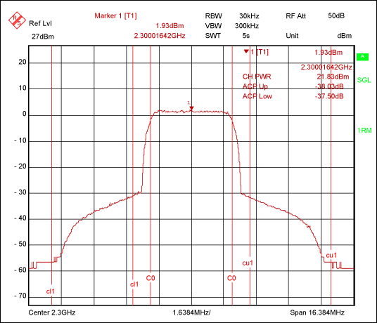
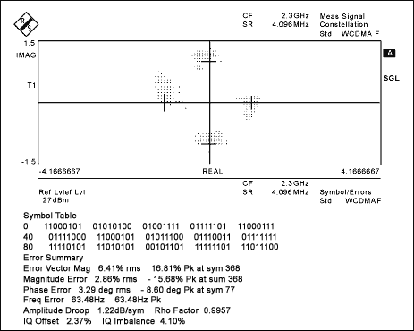
The measurement results of ACPR and EVM are shown in Figure 2 and Figure 3, respectively. The LO PLL synthesis frequency is 1150MHz. Turn on the LO frequency multiplier and set the VGA tuning voltage to + 2.5V. The ACPR measured at 4.9MHz bandwidth is less than -38dBc. The channel power obtained at the antenna port of the duplexer is +21.8 dBm. The minimum EVM is 5.9%, the typical value is 6.6% RMS, and the maximum value is 7.9% RMS.

Figure 2. The spectrum of the transmitter antenna port

Figure 3. Constellation diagram and EVM conclusion of the transmitter antenna port signal
The MAX2721 is ideal for broadband transmitter applications in the 2.4GHz band. This device has unlimited potential, it has a wide baseband bandwidth, integrated LO frequency multiplier, variable gain amplifier and a high linearity drive amplifier, as a basic building block is very suitable for use in low-cost transmitters. The test data at 2.3GHz shows its excellent EVM and ACPR performance in the WCDMA environment.
The Lightning To Usb Cable which 8 Pin connector with a lightning end has lightning-fast data transfer, syncing , and charging .
When you use the Iphone Usb Cable you should connect the Lightning Adapter to your IOS device and connect the USB side into a wall adapter or USB hub to charge or your computer to sync data .
Apple Lightning To Usb Cable connects your digital product to your computer`s USB port for syning and battery charging .
It also connects to digital product USB power adapter for convenient charging from a wall outlet.
This data cable can be connected to all the smart devices with MICRO interface to your computer USB port for sync and charging.
The lightning to usb cable designed to fit into virtually all cases .
We have always found pride in our dependable services, competitive prices, prompt delivery and continual product development. Based on clear vision, Baisiwei is creating a bright future with our customers.
We hope that we can become your trustful supplier with the best quality Lightning to usb cable products at competitive prices. With technology innovation to realize the high-end modern civilized life is the permanent target of our continuous development.
Lightning To Usb Cable
Lightning To Usb Cable,Usb Apple Charger Cable,Apple Lightning To Usb Cable,Usb Data Charging Cable,Lightning To Usb Cord
Hebei Baisiwei Import&Export Trade Co., LTD. , https://www.baisiweicable.com