As lighting technology moves from extremely power-hungry incandescent lamps to cold cathode lamps (CCFLs) to the current light-emitting diode (LED) lamps, it is clear that the end user is willing to be more green. At the same time as paying higher costs, they also have an inherent expectation that longer life and higher reliability will be the net benefit of their investment.
While meeting these expectations, LED design engineers must consider the different variables that affect the performance and longevity of their products. From power management to power density, to overvoltage and overtemperature protection, the uniqueness of LED technology brings new challenges that are outdated by older technologies.
With improved wafer design and materials, LED technology has grown rapidly, enabling it to rapidly evolve to brighter, more energy efficient, longer lasting light sources and to be used in a wider range. Despite the increasing popularity of technology, there is still the fact that excessive heat and improper application can significantly affect LED life and performance.
High-brightness LEDs (HB LEDs) are energy-efficient, cost-effective devices that ensure the next generation of lighting solutions. From architectural lighting to automotive lighting to backlighting of various display devices, and new consumer electronics such as flashlights in camera phones, the use of HB LED lighting continues to grow.
Overcurrent conditions in HB LED lighting systems
LED light output varies with wafer type, package, efficiency per wafer lot, and other variables. LED manufacturers use terms such as high brightness to describe the density of LEDs. HB LED drivers can be powered by linear or switched power supplies. A linear driver is most suitable when the supply voltage is slightly greater than the load voltage, and the resistor is used to limit its current. Switched power supplies are also used frequently because they are more efficient.
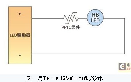
Typically, current sense resistors provide feedback to the current regulation controller to monitor the current supplied to the HB LED. Another alternative solution is to use a polymer positive temperature coefficient (PPTC) component to limit the current flowing through the LED.
As shown in Figure 1, a PPTC component is one of a series of elements in a circuit. Typically, the resistance of a PPTC component is less than the rest of the circuit, with little or no effect on normal circuit performance. However, once an overcurrent condition occurs, the component increases resistance (tripping) and reduces the current in the circuit to a current value that any circuit unit can safely carry. This change is caused by a rapid rise in the temperature of the component brought about by the I2R heat treatment.
The component will remain in its trip or latched state until the fault is removed. Once the power supply connected to the circuit is reclosed, the PPTC component resets and allows the current to resume flowing, allowing the circuit to resume normal operation. When PPTC components are unable to prevent a fault from occurring, they react quickly to limit the current to a safe level to prevent subsequent damage to downstream components. In addition, their small form factor makes them easy to use in space-constrained applications.
Unlike traditional lighting, thermal management is an important design consideration because HB LEDs are extremely heat sensitive. In order to improve reliability and working life, the PN junction cannot allow an increase in the conduction temperature. Since the PPTC component uses a hot start, any change in temperature around the component can affect its performance. As the temperature around the component increases, less energy requires the component to trip, so it can clamp the current value and lower it.
PPTC component work process
The PPTC circuit protection element is made of a semi-crystalline polymer and conductive particles. At normal temperatures, these conductive particles form a low resistance network structure within the polymer. However, if the temperature rises to the switching temperature (Tsw) of the element, whether the condition is caused by a large current or due to an increase in the ambient temperature, the crystalline substance in the polymer will melt and become an amorphous substance. The increase in volume that occurs during the melting phase of the crystal phase causes the conductive particles to separate under the action of the hydraulic force and causes a large nonlinear growth in the resistance value of the element.
Typically, the resistance value will increase by three or more orders of magnitude. The increased resistance value reduces the amount of current flowing through the fault condition to a lower steady-state level, thereby protecting the equipment within the circuit. The PPTC component will remain latched (high resistance) until troubleshooting and circuit power is removed; the PPTC component will return to a low resistance state after the conductive composite has cooled down and recrystallized.
Under normal operating conditions, the heat generated or dissipated by the PPTC component is in a relatively low temperature equilibrium state, as indicated by point 1 in FIG. When the ambient temperature is constant and the current flowing through the component increases, the amount of heat generated by the component increases. If the increased current is negligible and the heat generated can be lost to the environment, the component will stabilize at a higher temperature, as shown by point 2 in Figure 3.

Figure 2: The PPTC component protection circuit transitions from a low resistance state to a high resistance state in response to an overcurrent or overtemperature condition.

Figure 3: Typical operating curve for a PPTC component.
Conversely, if the current is not increased but the ambient temperature rises, the component will stabilize at a higher temperature and may reach point 2 as in the texture map again. The second point may also be the result of a combination of current and temperature increase. As current, temperature, or a combination of both increases further, it will cause the component to heat up and reach a temperature at which the resistance increases rapidly, as shown in point 3 of the figure, which is the so-called low-end inflection point of the curve. Any further increase in current or ambient temperature will cause the component to generate heat faster than it dissipates heat into the environment, causing its temperature to rise rapidly.
At this stage, a very large increase in resistance will occur with very small temperature changes, as shown between points 3 and 4 in the figure. This is a normal working area when the PPTC element trips. An increase in resistance results in a corresponding decrease in the current flowing through the circuit.
Since the temperature change between point 3 and point 4 is very small, this relationship will remain until the component reaches the upper inflection point of point 4 on the curve. As long as the externally applied supply voltage remains at this level, the component will remain latched in the trip state. Once the applied voltage is disconnected and the power loop is started, the PPTC component will be reset to the low-impedance state and the circuit will return to normal operation.
Figure 4 illustrates the circuit that protects the HB LED lighting system before and after the PPTC trips. This figure shows how the current is reduced after a trip to protect the circuit from overcurrent and overtemperature conditions.
Figure 4: Circuit state before and after the PPTC component trips
Meets Class 2 power safety standards
The use of a second type of power supply in a lighting system can be an important factor in reducing costs and increasing flexibility. Power supplies that are inherently restrictive, such as transformers, power supplies, or batteries, may contain protection components as long as they do not depend on the output limitations of the second type of power supply.
A non-self-limiting power supply, by its definition, has a discrete protection element that automatically interrupts the output when the current and energy outputs reach a predetermined value.
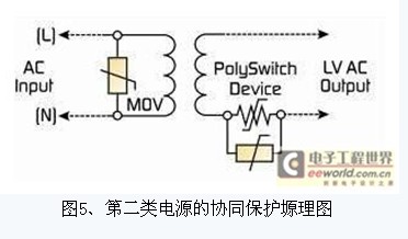
A wide variety of circuit protection components provide protection for Class 2 power supplies for LED lighting applications. Figure 5 illustrates the work of a collaborative protection strategy that uses an MOV on the AC input and a PolySwitch PPTC component on the output circuit branch. It can be seen that the manufacturer meets the UL1310 specification section 35.1 for switches and Overload test requirements for control devices.
Summary of this article
Self-resetting PPTC components have demonstrated effectiveness in a variety of HB LED lighting system applications. As with conventional fuses, they limit current when they exceed the rating. However, unlike conventional fuses, PPTC components can be reset after troubleshooting and power reclosing. Thanks to its hot start, it can prevent damage caused by the circuit under over-temperature conditions. This unique feature allows designers to increase the reliability and average life of lighting systems, as well as reduce component count and design complexity.
As with any circuit protection strategy, the effectiveness of a solution will depend on various specific design considerations for each different line layout, board type, specific component, and specific application. TE Circuit Protection works with OEMs to select and implement best practices.
Control impedance PCB
Many customers asked us what information we need for impedence control PCB.Here,there are two types for PCB manufacturer,a is single impedance ,just one trace ,two holes .and b is differential impedance,it always go with 1 pair (two trace with same width and space). For single impedance,you just tell us the trace width one which layer and what value you require .For differential impedance,trace width/space,layers and value. Our experience engineers will calculate following your instruction with Polar software.We may change trace width/space or stackup ,but please do not worry, if any changes,we will send you to approve before proceeding. Generally,the tolerance is 10%,and more accurate is 8% .All impedance boards ,we will test here and report.
Impedance Control Board,Impedance Controlled PCB,Gold Fingers PCB,Impedance Control PCB
Storm Circuit Technology Ltd , http://www.stormpcb.com