In the fields of medical equipment, automotive instrumentation, and industrial control, when equipment design involves strain gauges, sensor interfaces, and current monitoring, precision analog front-end amplifiers are often required to extract and amplify very weak real signals and suppress common Unwanted signals such as mode voltage and noise. First, designers will focus on ensuring that accuracy parameters such as device-level noise, offset, gain, and temperature stability meet application requirements.
The designer then selects the front-end analog device that meets the total error budget based on the above characteristics. However, there is a frequently overlooked problem in such applications, namely high frequency interference caused by external signals, also known as "electromagnetic interference (EMI)." EMI can occur in a variety of ways, primarily by the final application. For example, an instrumentation amplifier may be used in a control board that interfaces with a DC motor, and the current loop of the motor contains power leads, brushes, commutators, and coils, which typically emit high-frequency signals like an antenna, and may A small voltage that interferes with the input of the instrumentation amplifier.
Another example is current sensing in automotive solenoid valve control. Solenoid valves are powered by the vehicle's battery through long wires that act like antennas. A series shunt resistor is connected to the wire path, and then the voltage across the resistor is measured by a current sense amplifier. A high frequency common mode signal may be present in the line, and the input of the amplifier is susceptible to such external signals. Once affected by external high-frequency interference, the accuracy of the analog device may be degraded and the solenoid valve circuit may not be controlled. This state of performance in the amplifier is that the amplifier output accuracy exceeds the error budget and the tolerances in the data sheet, and in some cases may reach the limit, causing the control loop to turn off.
How does EMI cause large DC offsets? It may be the case that many instrumentation amplifiers can exhibit excellent common-mode rejection in the frequency range up to tens of kilohertz depending on the design. However, when an unshielded amplifier is exposed to tens or hundreds of "megahertz" RF radiation, problems can occur. At this point, the input stage of the amplifier may be asymmetrical rectified, resulting in a dc offset. After further amplification, it will be very noticeable, plus the gain of the amplifier, even reaching the upper limit of its output or part of the external circuit.
Example of how high frequency signals affect analog devices
This example will detail a typical high-side current sensing application. Figure 1 shows a common configuration for monitoring solenoid valves or other inductive loads in automotive applications.
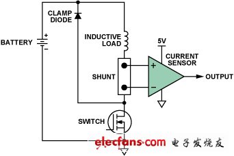
Figure 1. High-end current monitoring
We studied the effects of high frequency interference using two current sense amplifier configurations with similar designs. The functions and pinouts of the two devices are identical; however, one of them has an internal EMI filter circuit and the other does not.
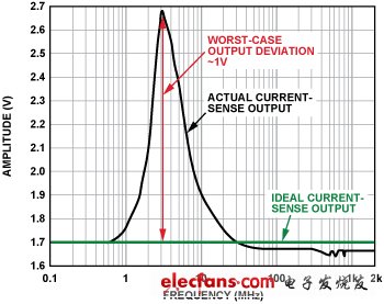
Figure 2. Current sensor output (no built-in EMI filter, forward power = 12 dBm, 100 mV/divide, DC output peaks at 3 MHz)
Figure 2 shows the deviation of the DC output of the current sensor from its ideal value as the input changes over a wide frequency range. It can be seen from the figure that the deviation is most significant (>0.1 V) in the frequency range from 1 MHz to 20 MHz, and the DC error reaches a maximum value (1 V) at 3 MHz, which is 0 V to 5 V in the amplifier. A large proportion of the output voltage range is occupied.
Figure 3 shows the results of the same experiment and configuration when using another pin-compatible current sensor with the same circuit architecture and similar DC specifications as the previous example, but with an input EMI filter circuit. Note that the voltage range has been expanded by a factor of 20.
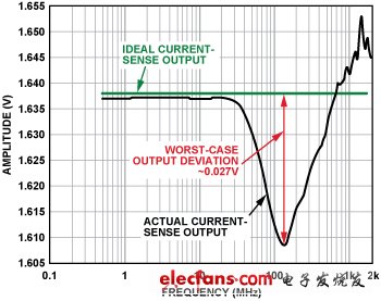
Figure 3. Current sensor output (built-in EMI filter, forward power = 12 dBm, 5 mV/divider, DC output peaks at >100 MHz)
In this case, the error is only about 3 mV at 40 MHz, and the peak error (greater than 100 MHz) is less than 30 mV, and the performance is improved by 35 times. This clearly shows that the built-in EMI filter circuit helps to significantly improve the current sensor protection from the high frequency signals present at the input. In practical applications, although the severity of EMI is not known, if a current sensor with built-in EMI filtering is used, the control loop will actually remain within its tolerance.
Both devices were tested under exactly the same conditions. The only difference is that the AD8208 (see “Appendixâ€) has an internal low-pass RF input filter on both the input and power pins. Adding such components to the chip seems trivial, but since the application is typically controlled by PWM, the current sense amplifier must be able to withstand a continuous switching common-mode voltage of up to 45 V. Therefore, to maintain accurate high gain and common mode rejection, the input filters must be closely matched.
| About Glass Fiber Covered Flat Aluminium Wire |
Packaging DetailsDifferent size bobbin with export carton/wooden box on pallet
or as customer's requirement.
Fiber Glass Covered Aluminum/Copper Wire is according to customers` requirement, aluminum/Copper conductor is evenly covered with one or two layers of non-alkali fiberglass, then it`s impregnated in compatible insulating coating of required thermal class baked to make a whole between fiberglass and aluminum/Copper conductor

- Excellent resistance to mechanical
- Suitable in lightweight designs
Glass Fiber Covered Flat Aluminium Wire
Rectangular Aluminum Wire,Glass Fiber Covered Flat Aluminium Wire,Fiberglass Covered Flat Aluminum Wire,Fiberglass Covered Aluminum Wire
HENAN HUAYANG ELECTRICAL TECHNOLOGY GROUP CO.,LTD , https://www.huaonwire.com