USB has been in existence for more than a decade since it was launched in 1996. The earliest USB 1.0 speed was only 1.5Mbps. After two years, it was upgraded to USB 1.1, and the speed was greatly increased to 12Mbps. However, today's products of this type include mouse. The outside is almost extinct. In recent years, the widely used USB 2.0 interface products have reached 480Mbps, which is 40 times that of USB 1.1, but the speed of USB 2.0 has long been unable to meet the needs of high-definition audio and video applications.
At the end of April 2012, with the release of Intel's native support for USB 3.0, the new generation of ivy bridge chipset has made USB3.0 go down the altar. The cost reduction makes consumers affordable, affordable, and greatly improved. In addition, the industry leader Microsoft will launch a new Windows 8 in 2012, which will load USB3.0 native drivers, which will enable users of USB3.0 master chip to obtain better compatibility, and also drive computer and chip suppliers. Large-scale deployment of USB 3.0 related products. In particular, the USB 3.0 interface greatly enhances the performance bottleneck of the USB 2.0 interface, and uses PCIe technology to regain the specification advantages of the external high-speed interface. In addition, the support of the host chip technology is becoming more and more mature, and will be heavily loaded in PCs and notebooks, attracting more. Multi-vendor supports USB 3.0 high-speed interface, and USB3.0 interface will usher in the era of universal popularity.
At present, there are many USB3.0 specifications of electronic products and peripherals on the market. The maximum transmission bandwidth of USB3.0 is up to 4.8Gbps, and the transmission speed is 10 times higher than that of USB 2.0. The biggest advantage is that USB 3.0 retains the plug-and-play function. It can also be used as a power source and is compatible with USB 2.0. In addition to providing more profit for manufacturers, it also allows users to easily upgrade and enjoy its innovative features. In addition to host computers such as desktop computers and notebook computers, USB 3.0 will also be used in a variety of computer peripherals, including USB flash drives, external hard drives, and so on. According to research firm IDC, by 2015, USB3.0 shipments will accelerate to double to 2.3 billion, of which 50% will be applied to storage functions, which will reach 40 billion yuan. The industry believes that the proportion of PCs and notebooks loaded with USB 3.0 high-speed interfaces will increase significantly in the second quarter of 2012. The reason is that USB 3.0 multi-host chip solution costs continue to be low, on the other hand, USB 3.0 peripheral products It is no longer limited to external hard drives, USB flash drives, etc. It is expected that mobile phones, tablets, digital cameras, etc. will be launched.
High performance USB3.0 physical layer IP
The first product of Zhiyuan Technology in the USB3.0 physical layer IP is the world's first USB3.0 prototype exhibited by the USB-IF Association at Intel's IDF in August 2008. As shown in Figure 1, the USB 3.0 physical layer IP mainly includes two parts: PMA (Physical Medium Attachment Sublayer) and PCS (Physical Coding Sublayer).
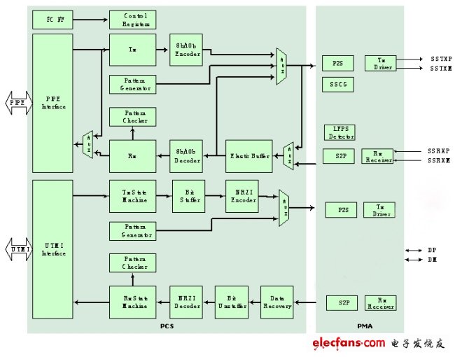
Figure 1: USB 3.0 physical layer IP mainly contains PMA and PCS.
The PCS part mainly performs auto-negotiation (Auto negoTIaTIon) and 8b/10b encoding and decoding. Auto-negotiation selects common transmission parameters, such as speed and flow control, through two connected devices. In this process, the connected devices first transmit at their own maximum speed, and then negotiate to find the most supported by both sides. High speed as the transmission mode. After determining the transmission mode, the PCS encodes and decodes the transmitted and received information in order to make it easier for the receiver to recover the signal.
The PMA section primarily handles analog high-speed signals at speeds up to 5 Gbps. In terms of transmission lines, USB 3.0 supports up to 3 meters of four-wire differential signal lines and 11-inch PCBs. As shown in Figure 2, the 5Gbps signal is transmitted on the long cable in differential signal mode to avoid signal interference and reduce electromagnetic interference (EMI) problems. The PMA circuit is divided into the following six main modules.
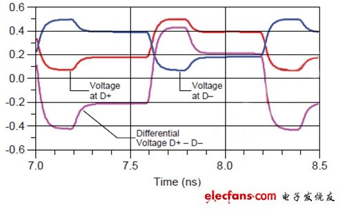
Figure 2: Differential transmission of 5Gbps signals reduces electromagnetic interference.
Parallel to Serial (P2S): Converts a lower speed parallel signal into a high speed serial signal.
Spread Spectrum Clock Generator (SSCG): As shown in Figure 3, triangulation is performed at a low speed at a transmission speed of 5 Gbps. This spread-spectrum action can reduce the electromagnetic interference problem when the signal is transmitted on the transmission line and the PCB.
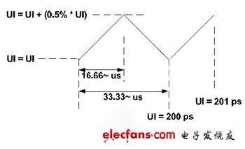
Figure 3: 5Gb/ps transmission speed to the low speed triangle spread spectrum.
TX Driver: This module converts 5Gbps high-speed single-ended signals into high-speed differential signals, and produces 3.5dB/6dB de-emphasis according to USB3.0 specification. It is enhanced by 3.5dB/6dB de-emphasis on the TX port. The energy of the frequency avoids transmission loss and makes the opening of the eye diagram smaller.
LFPS Detector (Low Frequency Period Signal Detector): If the link is in some idle state, the low frequency periodic signal (LFPS) can be used for communication through the low frequency periodic signal. The power consumption of this method is significantly lower than that. SuperSpeed ​​signal transmission method. In fact, whether the host or the device sends the LFPS, it will exit the idle mode.
RX Receiver: This receiver contains an equalizer module and a clock-data recovery module. The equalizer receives high-speed 5Gbps high-speed signals and compensates for high-frequency energy lost due to transmission, so that the clock-data recovery module has a large opening when latching data.
Serial to Parallel (S2P): Converts high-speed serial signals received into high-speed parallel signals.
Dog Fence,Wire Fence,Petsafe Fence,Best Wireless Dog Fence
Elite-tek Electronics Ltd , https://www.aetertek.ca