At present, in the development and development of the H.324 system, two methods are commonly used: one is to develop a pure software H.324 system, that is, a PC-based system; the other is to use a programmable video signal processor. To achieve the functions of the H.324 system. The latter approach is very flexible and allows different applications to be developed on the same hardware platform. The solution proposed in this paper is a realization method based on programmable digital signal processing chip. This solution can develop a stand-alone videophone terminal, and can be applied to communications, monitoring, and the like.
1 Functional elements of the H.324 terminal
The H.324 recommendation specifies some of the functional elements of the system. H.324 terminal configuration and its peripheral elements are shown in Figure 1, including terminal I / O devices, Modem, GSTN network, MCU and other system operating entities. H.324 implementation does not require every functional element .
The H.324 videophone terminal framework proposal includes the following five aspects:
·H.263/H.361 video codec
·H.223 channel multiplexing/demultiplexing
·H.245 system control
·G.723.1 audio codec
·V.34 Modem? Modem

The multimedia information flow in the H.324 terminal is divided into video, audio, data and control flow:
The video stream is a continuous stream of code that transmits color moving images. During transmission, the bit rate of the video stream varies depending on the needs of the audio and data channels.
? 2? The audio stream is real-time, but may be appropriately delayed while processing at the receiving end to maintain synchronization with the video stream. To reduce the average bit rate of the audio stream, voice activation can be used.
The data stream can represent still images, faxes, documents, computer files, undefined user files, and other data streams.
The control flow transfers control commands and instructions between the peers. The control of the terminal to the modem is subject to the V.25ter recommendation (using an external modem connected via a separate physical interface). End-to-end control is subject to H.245 recommendations.
2 H.324 terminal implementation
H.324 is just a framework agreement, and there are many ways to implement it. Dedicated circuits can be designed according to the H.324 standard. Although this method has the characteristics of fast processing speed and convenient application, this method has great limitations. Because a dedicated circuit can only be designed for a specific function, it has the disadvantages of high development cost and difficulty in improving functions. Among the existing or under-developed products, pure software or computer-based methods are generally adopted, or programmable digital signal processors are used, or two methods are combined to develop and implement the H.324 system. The system developed by the author of this article is mainly realized by using the W90K series chip, which is realized by a programmable digital signal processor. Figure 2 is a block diagram of the principle based on the W90210 terminal.
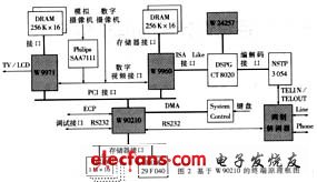
The development board is divided into a video codec module, an audio codec module, a code stream multiplexing and system control module, a video display module, and a modem module. These modules are complemented by peripherals such as video display and sound input playback to complete the H.324 videophone function.
·Video codec chip W9960 This chip mainly completes the video codec function. The chip is especially suitable for the H.263/H.261 function, and can complete the coding of CIF, QCIF, SQCIF and other formats. Solidified in the chip is the standard H.263 video codec, which works in unrestricted motion vectors and PB frame modes. The multiplex control chip on the development board controls the start, stop, and codec mode conversion of the codec. The W9960 has a digital video interface that supports digital camera input. In addition, the chip also has a PCI interface for exchanging data with the development board main CPU and the display module.
· Audio codec chip CT8020 This chip completes the audio codec function. The chip has G.723.1 microcode, which can encode audio raw data (16bit? 8kHz) into G. 723.1 data frame and can decode G. 723.1 data frame into audio original data. The audio codec module with CT8020 as its core and its peripheral devices can receive the voice input code and receive the G. 723.1 code stream for decoding and playback. The module output stream can work at 6.3Kbit and 5.3Kbit. The initialization of the module and the start of work stop and the change of working mode can be realized by calling its API function.
· Video Display Module This module is mainly composed of W9971 and its peripheral devices. The module receives the input digitized image signal to display a local image or receives W9960 decoded data to display the far end image. The W9971 chip can also manage display modes such as image size, position, hue, contrast, and more.
Video Input Module This module is mainly composed of a digital camera or an analog camera and SAA7111 chip. The function of the SAA7111 is to convert the input image signal of the analog camera into a digital image signal, which is input to the video display module for displaying the local image, and the signal is also input to the video codec module, and the signal is encoded and then multiplexed and transmitted. To the far end.
Modem Module This module mainly performs voice input and modulation functions.
· Multiplex Control Module This module is the core of the entire terminal and is mainly composed of the chip W90210 and its memory. The main function of the module is to complete the initialization of each function module on the board, receive the code stream output by the audio codec module and the code stream output by the video codec module, and reuse the code stream and system control information according to the H.223 standard. After modem modulation, it is transmitted on the GSTN network. The more important function of this module is to control the operation of each functional module on the entire board. The functions of the H.229 and H.245 protocols specified in the H.324 system are also implemented in this module.
3 terminal software development
This terminal is developed and implemented under the embedded real-time operating system Supertask. The relationship between the hardware and the operating system and the developed application is shown in Figure 3.
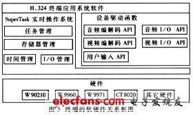
Figure 3 shows the software and hardware block diagram of the H.324 terminal in this article. The hardware of the development hardware platform is at the bottom of the system and is managed by the SuperTask real-time operating system. Based on the operating system, hardware driver functions such as driver functions for audio and video codecs and driver functions for input/output modules are developed, which are called when the application system is developed. The software in the above terminal is developed on the basis of these driver functions, using the services of the operating system.
H.324 terminal application system software
In the SuperTask real-time operating system, the H.324 terminal system is functionally divided into several independent tasks? The tasks are connected as a complete system as a whole. Figure 4 is the relationship between the various tasks.

Jewish Candle is 3.8g Candle . Small Box Jewish Candle is high quality with strong box . it is very popular in Israel market . we usually called Multicolor Jewish Candle or 3.8G Jewish Candle . The Dia of Jewish Candle is 0.8cm , Length is 9.5cm .Box can do any colors or as your requirments . the noraml package is 44pcs/box 50boxes/ctn . it depends on you .
Fast shipment time, high quality product, and fast respond to any customer, we always online waiting your response. all the clients are our important person.
Jewish Candle
Jewish Candle,3.8G Jewish Candle,Small Box Jewish Candle,Multicolor Jewish Candle
Shijiazhuang Zhongya Candle Co,. Ltd. , https://www.zycandlefactory.com