**Introduction**
Portable power supply design requires a system-level approach. When developing battery-powered devices such as mobile phones, MP3 players, PDAs, PMPs, and digital still cameras, an improperly designed power system can significantly impact the overall performance and architecture of the device. The integration of component selection, software design, and power distribution must be carefully considered. Additionally, from a power-saving perspective, it is essential to optimize energy usage throughout the system. A low dropout linear regulator (LDO) with enable control is often an ideal choice for such applications.
**Power Requirements for RF Circuits**
Most baseband chipsets in cellular phones require three distinct power supplies to support digital circuits, analog circuits, and peripheral interfaces. The digital circuits typically operate at voltages ranging from 1.8V to 2.6V. When the lithium-ion battery voltage drops below 3.2V to 3.3V, the phone usually shuts down. In this case, the LDO needs to maintain a dropout voltage of at least 500mV to 600mV, which is relatively low. Additionally, the digital circuits do not demand high noise performance or high PSRR from the LDO, but they do require very low quiescent current under light load conditions.
The analog circuits within the baseband processor are usually powered between 2.4V and 3.0V, with a dropout voltage of 200mV to 600mV. These circuits require LDOs with high low-frequency ripple rejection—especially in GSM phones operating at 217Hz—to eliminate ripples caused by RF power amplifiers. Moreover, the LDOs should have low quiescent current specifications to maintain efficiency.
For RF power supplies, the receive and transmit voltages typically range from 2.6V to 3.0V. Components like low-noise amplifiers (LNAs), mixers, phase-locked loops (PLLs), voltage-controlled oscillators (VCOs), and intermediate frequency (IF) circuits all require a low-noise, high-PSRR LDO. The performance of VCO and PLL circuits directly influences key RF parameters such as transmitted signal purity, receiver selectivity, transceiver noise, and digital circuit phase error. Any noise introduced into the oscillator can affect its phase and amplitude characteristics, and the oscillator loop may further amplify this noise, potentially modulating the carrier signal.
**LDO Noise and Power Supply Rejection Ratio**
An LDO is a micropower, low-dropout linear regulator known for its low self-noise and high power supply rejection ratio (PSRR). Figure 1 shows the block diagram of a typical linear regulator.

PSRR is an AC parameter that measures how well an LDO suppresses input ripple at the output. It differs from noise, which generally refers to interference in the 10 Hz to 100 kHz range. The formula for PSRR in decibels is:
$$ \text{PSRR} = 20\log\left(\frac{\Delta V_{in}}{\Delta V_{out}}\right) $$
When the input voltage changes by 1V, and the output changes by just 1mV, the PSRR is 60dB, indicating strong ripple suppression.
The output noise of an LDO is influenced by internal design and external bypass and compensation components. As shown in Figure 1, the main source of noise is the reference voltage, which is amplified at the output. The output noise $ V_n $ can be expressed as:
$$ V_n = \frac{R_1 + R_2}{R_2} \times V_{ref} $$
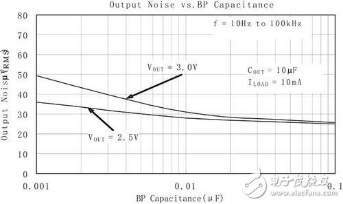
A bypass capacitor connected to the reference voltage helps reduce reference noise. Typical values for ceramic capacitors range from 470pF to 0.01mF. However, larger bypass capacitors can slow down the output voltage rise time, so care must be taken when selecting their values.
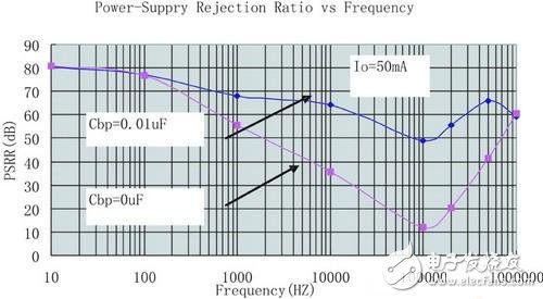
Other factors affecting LDO output noise include internal poles, zeros, and the output load. Increasing the output capacitance or reducing the load can help lower high-frequency noise. Figures 3 and 4 illustrate the effect of the reference bypass capacitor on the output noise and PSRR of the SGM2007.
Additionally, LDOs require external input and output capacitors. Large capacitors with low equivalent series resistance (ESR) improve overall PSRR, noise performance, and transient response. Ceramic capacitors are preferred due to their low cost and failure mode (open circuit), unlike tantalum capacitors, which can fail short-circuited. The ESR of the output capacitor affects stability. Ceramic capacitors typically have ESR in the range of 10mΩ. X5R and X7R dielectrics are recommended for better temperature stability.
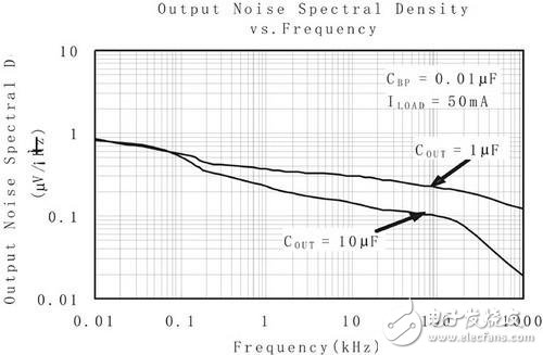
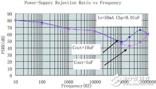
Figures 5 and 6 show the effect of the output capacitor on the noise and PSRR of the SGM2007. Larger capacitors generally reduce output noise and increase PSRR over a wide frequency range.
ZGAR Glo-X Prefilled Cartridge
Zgar International (M) SDN BHD , https://www.zgarvape.com