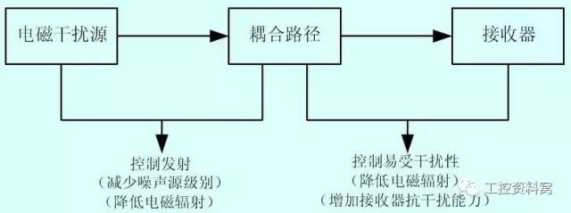
Recommendations for Preventing Electromechanical Interference
To minimize electromagnetic interference and ensure accurate measurements, several key installation practices should be followed. First, power cables and signal cables must be routed in separate metal conduits to prevent cross-talk. These conduits should be connected and grounded at intervals of approximately 100 meters. A minimum distance of 2 meters between different types of conduits is also required to reduce the risk of interference.
Second, switchgear should be positioned as far away as possible from the instrumentation system. It is advisable to use a dedicated stand or enclosure to isolate these components. This helps maintain signal integrity and reduces the potential for electrical noise affecting sensitive equipment.
For proper shielding of instruments, the "Faraday cage" principle should be applied. This means that all conductors should be fully enclosed in a continuous, conductive shield. The shield should cover at least 80% of the surface area and be made of heavy-duty woven material. The shield should only be grounded at one end—typically at the power supply side—and connected through a grounding box or cabinet to ensure a stable reference point.
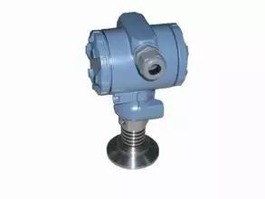
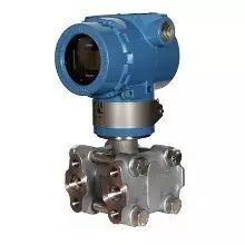
Pressure Transmitters
When installing pressure transmitters, it's important to avoid placing them in areas where flow disturbances could affect readings. Specifically, the pressure-tapping device should not be located in straight sections of pipe, bends, corners, dead zones, or regions with vortices that might distort static pressure.
Additionally, when mounting the pressure tap, the tube should not extend into the fluid flow, especially if it is perpendicular to the direction of flow. The edges of the tapping point should be smooth to prevent turbulence. All connections and fittings should be clean and free of burrs to ensure consistent performance.
For gas flows, the pressure tap should be installed on the upper half of a horizontal or inclined pipe. For liquid flows, it should be placed in the lower half, within 0–45° of the horizontal centerline. In steam applications, the tap should again be on the upper half, aligned with the horizontal centerline.
All pressure-receiving devices must have a single isolation valve, and the primary valve should be located close to the transmitter to allow for safe maintenance. The impulse line should be sloped to facilitate the drainage of air or condensate, with a minimum slope of 1:100. A drain valve should be installed near the pressure gauge to flush the line and remove any trapped air.
Before installation, the impulse line should be thoroughly cleaned and purged to ensure no blockages. All valves must be tested for tightness before and after installation. The line should be filled with water prior to operation, ensuring no air bubbles are introduced, which could compromise measurement accuracy.
For smart transmitters, always refer to the manufacturer’s manual for specific installation guidelines.
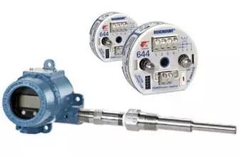
Temperature Transmitters
The temperature sensing element should be placed in a location that accurately reflects the medium’s temperature. Avoid positioning it near valves, elbows, or other obstructions that could create dead spots. The sensor should be installed at an angle so that the tip faces the direction of the fluid flow.
If the pipe diameter is 76 mm or smaller, consider expanding the pipe to accommodate the sensor. For horizontal pipes, platinum resistance thermometers should generally be installed horizontally or slightly downward to prevent dirt from entering. The sensing element should be centered in the pipe, extending 50–70 mm beyond the centerline.
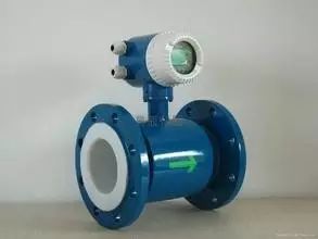
Electromagnetic Flowmeters
Environmental conditions such as temperature, humidity, and electromagnetic fields must meet the specifications of the flowmeter. The upstream and downstream straight pipe lengths should be maintained to ensure laminar flow. Typically, the upstream section should be at least 10D (where D is the pipe diameter), and the downstream section should be 3D–4D.
Chemical additives can affect the conductivity of the liquid, so they should not be injected upstream of the meter unless sufficient mixing time is provided. For vertical installations containing solids or slurries, the flow should move from bottom to top, and the electrode plane must remain parallel to the ground.
Grounding is essential for electromagnetic flowmeters. The working ground ensures that the sensor and the liquid share the same potential. A grounding ring is typically used to connect the liquid to the ground. Single-point grounding is recommended, with a resistance of ≤100 ohms. Signal cables should be grounded at the control room side.
Vortex Flowmeters
If the pipeline experiences vibration, additional supports should be added. For optimal performance, the flowmeter should be installed vertically or at an angle when the Reynolds number exceeds 2×10â´.
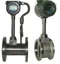
The flowmeter should be installed upstream of any valves, with at least 20D of straight pipe upstream and 5D downstream. If the valve is upstream, ensure a minimum of 20D between the valve and the flowmeter, and 5D downstream.
Additional considerations include maintaining 20D of straight pipe upstream of the flowmeter, especially if a gate valve is present. For expansion or contraction sections, ensure 10D upstream and 5D downstream. Pressure and temperature measuring points should be placed at appropriate distances downstream of the flowmeter.
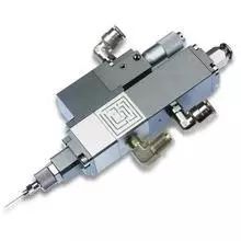
Power Concentration Transmitter
The transmitter should be installed in a location that avoids mechanical damage and vibration. The electronic unit should be placed in a cool, ventilated area and protected from moisture. A waterproof baffle is recommended. The transmitter should be as close as possible to the dilution water connection to minimize response time.
Installation distances should account for minimum stable sections of the slurry pipe. Typically, L1 = 10D and L2 = 5D. For certain pulp types, these values may need to be adjusted. The short pipe should be precisely aligned to ensure no protrusion from the slurry pipe.
The blade should be installed parallel to the slurry flow and without mechanical contact. All signal cables should be multi-core, shielded, and protected by galvanized steel pipes.
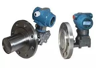
Flange Level Transmitter
The transmitter should be mounted at the bottom of the tank, avoiding areas with turbulent flow or near agitators or pumps. This ensures accurate level measurement without disturbance.
Dosing Valve
Valves with diameters between 50–250 mm can be installed in various orientations. For larger sizes, horizontal installation is preferred. The valve should be positioned to avoid damaging the slurry flow and should be protected from mechanical damage.
Input Level Transmitter
In stationary water applications like wells or pools, steel pipes are commonly used to insert the transmitter. The pipe should have multiple holes at different heights to allow for even water flow. In flowing water, the pipe should be oriented to capture the flow correctly. The transmitter should be installed vertically downward, away from inlets, outlets, and agitators.
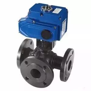
L-Type Three-Way Valve
Before installation, carefully verify the valve type, size, and flow path. Follow the manufacturer's instructions strictly to avoid misalignment or operational failures. Ensure that the valve is properly sealed and functions as intended.
Hp Probook Series,Hp Probook Lcd Back Cover,Palmrest Keyboard,Back Cover
S-yuan Electronic Technology Limited , https://www.syuanelectronic.com