Based on the design of vehicle odometer terminal, this paper discusses the anti-interference design method of electromagnetic compatibility under the existing experimental conditions, and achieves the principle of practical application of engineering. A targeted integrated design scheme was proposed, which was implemented to meet the electromagnetic compatibility of equipment and the internal compatibility of the system.
This article refers to the address: http://
With the increase of automotive microelectronic equipment, the sensitivity of semiconductor logic devices to electromagnetic interference is quite high. In addition, the line speed of automobiles and the wavelengths of relevant high field strength bands can be compared. These frequency bands have hidden dangers of causing strong electromagnetic interference to the vehicle electronic system. The on-board electromagnetic low voltage and high current load characteristics cause the switching process to generate a lot of pulse interference on the power supply line, further aggravating the electromagnetic environment. Therefore, in the actual automotive electrical design, electromagnetic compatibility design is often the key to design success.
How the odometer works and is disturbed
The working principle of the odometer is to count the number of pulses by the gear rotation of the sensor acquisition transmission part, and send it to the display terminal after data processing. This is the mileage we see. Figure 1
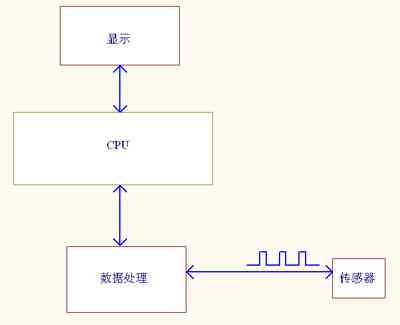
Figure 1 odometer work block diagram
However, the odometer does not match the actual number of miles at work, indicating how many actual kilometers are needed. That is to say, the odometer count signal is subject to external interference, which affects the measurement accuracy of the mileage; in order to find the disturbed part, the pulse signal collected by the oscilloscope observation sensor will induce different noise voltages under high frequency conditions. Affects the normal operation of the sensor pulse count signal. At the same time, through the comparison test in different electromagnetic environments, it is determined that the spontaneous harassment inside the car has a great influence on the normal operation of the system. Observing the sensor pulse counting signal through the oscilloscope shows that on the basis of the shielding measures of the sensor signal line, the equipment of other vehicle-mounted electrical appliances brings a glitch of 0.1V~1.7V in the sensor signal line, thereby affecting the accuracy of the odometer. As shown in Figure 2.
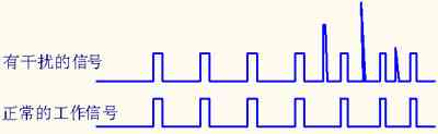
Figure 2 odometer interference and normal waveform
There are many sources of interference due to self-generated disturbances inside the car, such as wiper motor, fuel pump, spark ignition coil, air conditioner starter, intermittent disconnection of alternator cable connection, and some wireless electronic devices such as mobile phones and vehicles. Radio, etc. These types of sources of interference generated by a transient electric pulse of electromagnetic disturbance emitted to the environment caused by the interference of other devices. Therefore, it is more difficult to suppress the source of interference. In order to achieve the measurement accuracy of the odometer, it is more realistic to strengthen the anti-interference ability design of the odometer equipment.
In order to further verify the propagation path of the pulse interference, the odometer is separately powered in the laboratory, and the pulse signal is coupled to the power line and the signal acquisition line of the odometer through the coupling network, and the counting signals are all interfered, especially the signal acquisition line. The most obvious, the impact accuracy is greater. Figure 3
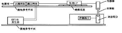
As shown in Figure 3, laboratory verification
the measures taken
2.1 Power supply filter voltage regulator
The power supply line in the car constitutes a complete circuit connection between the interference source and the sensitive device, and the interference signal can reach each power device through the power supply line. Therefore, filtering and voltage stabilization measures are taken in the power supply of the odometer to improve the ability to resist external interference. First, filter measures are taken on the power supply part of the odometer to prevent the shared power of many devices from crosstalking each other. After using the filtering method, the oscilloscope observes the strong coupled pulse interference on the power line during the test, and the glitch signal becomes significantly smaller. Circuit diagram shown in Figure 4 
Figure 4 power supply filter circuit
Diode D16 is mainly to prevent the positive and negative poles of the power supply from being mistakenly connected. Inductors L7 and L8 filter the power supply, and the filter and capacitor C11 cooperate to filter out spikes in the power supply. Diode D14 is a pulse-interference suppressor that quickly absorbs spikes that exceed the rated voltage, and the instantaneous pass current is large. Capacitors C12 and C13 further filter the power supply.
Second voltage regulation technology
The power supply module of the system and the vehicle power supply form a direct path, which is directly affected by external voltage and current fluctuations. In order to provide a stable voltage, the power supply should be considered as an important sensitive device. Currently, there are two kinds of regulated power supplies commonly used in the development of intelligent instruments: One is a series-regulated power supply provided by an integrated voltage regulator chip, and the other is a DC-DC regulated power supply, which is very effective in preventing other power-consuming equipment from interfering with the voltage fluctuations to the normal operation of the odometer. The circuit principle is shown in Figure 5. The input and output of this DC/DC module are completely isolated and have a wide input range. The allowable input range for DC/DC power supplies with a nominal input voltage of 12V is 9 to 18V.
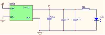
Figure 5 Input and output isolation of the DC/DC module
2.2 Digital filtering of signal lines
Due to the capacitive coupling between the wires and the inductive coupling of the electric field and magnetic field, it is also one of the main reasons for the interference of the odometer channel. Especially the signal lines are close to each other, which increases the chance of interference. If the odometer immunity performance design is not good, it can easily cause interference odometer signal. According to the above principle, in order to ensure the normal operation of the odometer, in the actual field operation, due to the pulse interference, a series of interference pulse signals with steep rising edges and narrow pulse width appear on the useful pulse signal, although at the signal input end The RC filter was taken, but the series of interference pulses were not filtered out until the useful signal was too slow to be used due to the rising edge, and the interference signal was hardly attenuated.
We take a separate signal processing circuit, the monostable circuit designed to improve the anti-interference ability of the odometer, the specific circuit shown in Figure 6. Principle is an anti-glitch circuit using a common monostable device and the D-type flip-flops, with the disturbance pulse on the input signal, the input waveform shown in (7) in the waveform A shown. Edge of the signal and impulse noise can trigger a monostable circuit generating a fixed output pulse width, so that the pulse width is smaller than the design of the circuit but greater than the width of the noise signal pulse width, then the input signal is generated by the monostable circuit in FIG. (7) The signal of waveform B in the middle. The output of the D type flip-flop waveform decisions terminal D and the terminal CL, while the two output terminals is high only when is high, (7) shown in waveform C in FIG final output waveform, the waveform of the output There is no additional impulse noise to achieve the filtering effect.
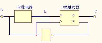
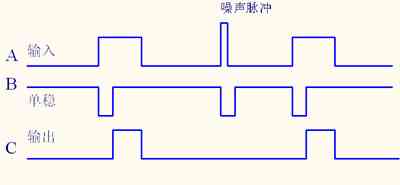
Figure 7
Practice has proved that the design of the monostable circuit and the D-type flip-flop makes the circuit's ability to resist external electromagnetic interference significantly enhanced, greatly improving the reliability of the product.
2.3 Measures taken by other parties
Because the electromagnetic environment in the car is more complicated, in order to avoid the hidden danger of mutual interference caused by electromagnetic coupling, in the odometer wiring, the signal line and the power line are separated as far as possible; the odometer signal line is twisted, and the shield of the cable is grounded at both ends. It does not interfere with adjacent wires or loops and can suppress possible interference of the magnetic field to weak signal loops.
to sum up
There are various loads on the automotive electrical system, including small impedance, high current resistance to the sexy load, small current, high voltage pulse generating device, and high frequency oscillating signal source, which are not only externally interfered with the emission. Source is also a source of interference for automotive electronics. In addition, due to the high maneuverability, the car may also be in various imaginable complex electromagnetic fields from low frequency to high frequency. The resulting electromagnetic interference coupling also affects the normal operation of the automotive electrical and electronic system. Automotive electronic design not only needs to protect sensitive equipment or devices in such a noisy environment, but also must standardize EMC design, improve electromagnetic compatibility of products, and ensure that noise from noise sources meets the requirements of the index.
Welcome to our FR4,G10 processing page. We could offer most kinds of FR4,G10 products processing for you.Like FR-4, G-10 sheet material, FR-4 , G-10 Tube/rods. also like CNC machining parts. Also,we can customize FR-4,G10 products according to your sample or blueprint.
The main difference between NEMA Grades G10 and FR4 is that FR4 is a fire retardant grade of G10. Therefore, FR4 can be safely substituted where G10 Cnc is called for, while G10 can never be substituted where FR4 is called for.

FR-4 & G-10 Processing,FR4 Fiberglass Lapping Carrier,Epoxy Fiberglass Cloth Tube,G10 Cnc
JinYuan Group-NingBo JinYuan Insulation Material Co.,Ltd , http://www.ccl-manufacturer.com